2-17
2-2 Wiring
SYSDRIVE MX2 Series USER'S MANUAL (3G3MX2-Axxxx)
2
Design
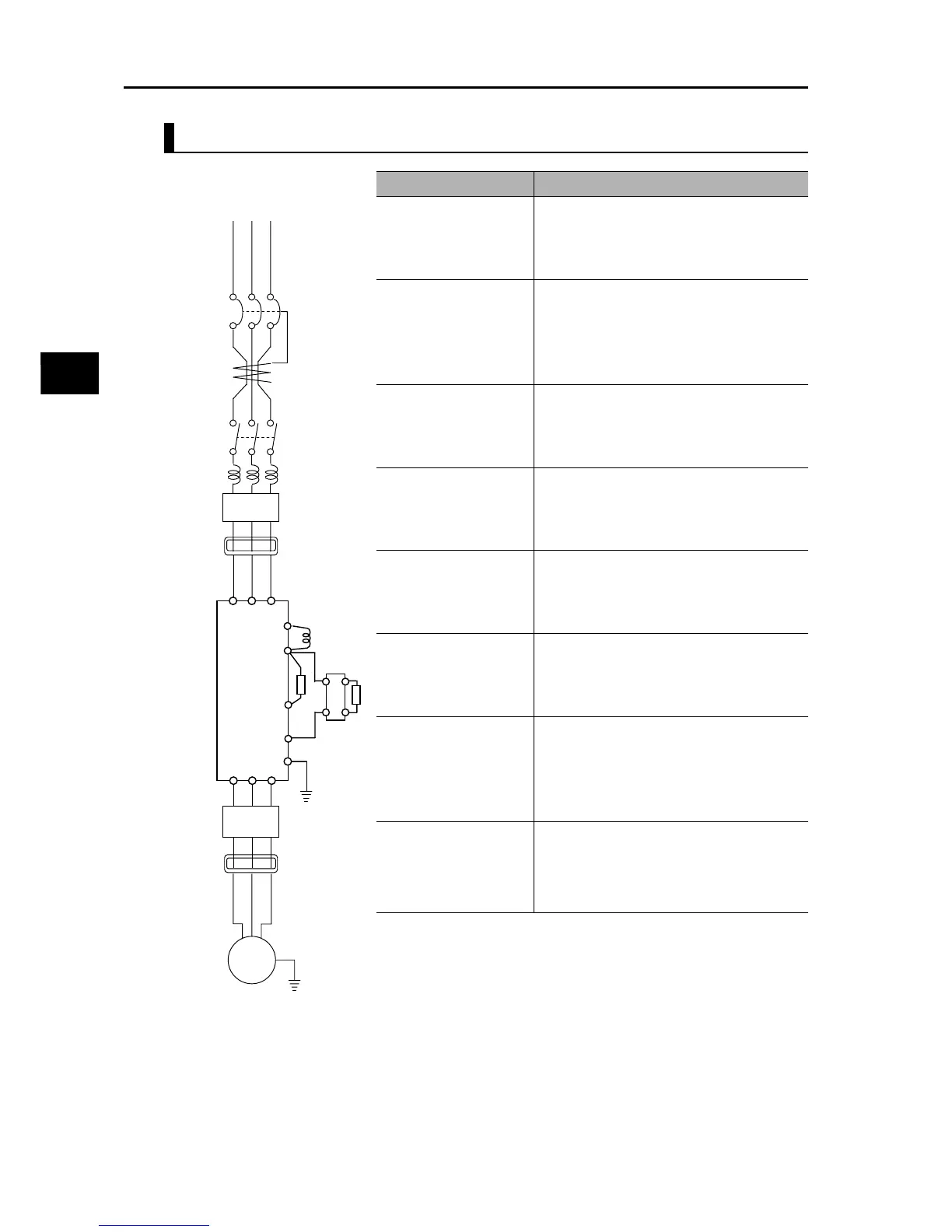
Main Circuit Connection Diagram
Name Function
(1) (2) (3) Refer to "Recommended Cable Size, Wiring
Device and Crimp Terminal" on page 2-15.
(4) AC reactor Apply this reactor as a harmonic suppression
measure, or when the imbalance ratio of
power supply voltage is 3% or more, power
supply capacity is 500 kVA or more, or power
supply voltage changes suddenly. It also
helps improve the power factor.
(5) Input noise filter This noise filter reduces the conducted noise
generated by the Inverter and traveling
through the wires. Connect it to the primary
(input) side of the Inverter.
(6) Radio noise filter When the Inverter is used, noise may
generate in a nearby radio, etc. through the
power wiring, etc. Use this noise filter to
reduce such noise (= reduce radiated noise).
(7) DC reactor This reactor suppresses the harmonics
generated by the Inverter.
(8) Braking Resistor
(9) Regenerative braking
unit
Use this Unit to increase the braking torque of
the Inverter to permit frequent ON/OFF
switchings, or decelerate a load whose
inertial moment is large.
(10) Output noise filter This noise filter is installed between the
Inverter and motor to reduce the radiated
noise emitted from the wires. Use it to reduce
radio interference in radios and TVs, or
prevent malfunctioning of measuring
equipment, sensors, etc.
(11) Radio noise filter Apply this noise filter to reduce the noise
generating on the output side of the Inverter
(both the input side and output side).
Power supply
(1)
(2)
ELB
(3)
Magnetic contacto