2-8
2-2 Wiring
SYSDRIVE MX2 Series USER'S MANUAL (3G3MX2-Axxxx)
2
Design
Analog
Sensor
input
S5/TH External
thermistor input
(also used as
multi-function
input terminal)
Connect an external
thermistor between the
SCs, to trip the Inverter
when a temperature error
occurs. (The inverter will trip
when the input from
thermistor is approx. 3 kΩ or
higher.) Since this input is
also used as the multi-
function input terminal,
setting of C005 is required.
For details, refer to
"Thermistor Trip Function"
on page 5-120.
PTC type
Output AM Multi-function
analog output
(voltage)
Specified signals can be
output using voltage signals
of 0 to 10 VDC.
AM
Digital
Power
supply
SC
Input signal
common
This is a common terminal
used by the internal power
supply, digital input and
analog input/output
terminals.
P24
Power supply
terminal for
input signal
24 VDC power supply for
contact input signal.This is
used as a common terminal
if the source logic is input.
Allowable max. current:
100 mA
PSC
Power supply
terminal for
input terminal
Sink logic input: Shorted
with P24
Source logic input: Shorted
with SC
To drive the contact input
using an external power
supply, remove the shorting
bar. For details, refer to
"Connection to
Programmable Controller
(PLC)" on page 2-22.
Input
Contact
S7/EB
S6
S5/TH
S4/GS2
S3/GS1
S2
S1
Multi-function
input terminal
Select 7 functions from
among 59, and allocate
them to terminals S1
through S7/EB. Both sink
and source logics are
supported. For details, refer
to "Connection to
Programmable Controller
(PLC)" on page 2-22.
Voltage between each
input and PSC
ON voltage: 18 V min.
OFF voltage: 3 V max.
Allowable max. voltage: 27
VDC
Load current: 5 mA (at 24
V)
S4/GS2
S3/GS1
Safety input Enabled when the safety
function selector switch is
turned ON. For details, refer
to "Safety Function" on
page 5-167.
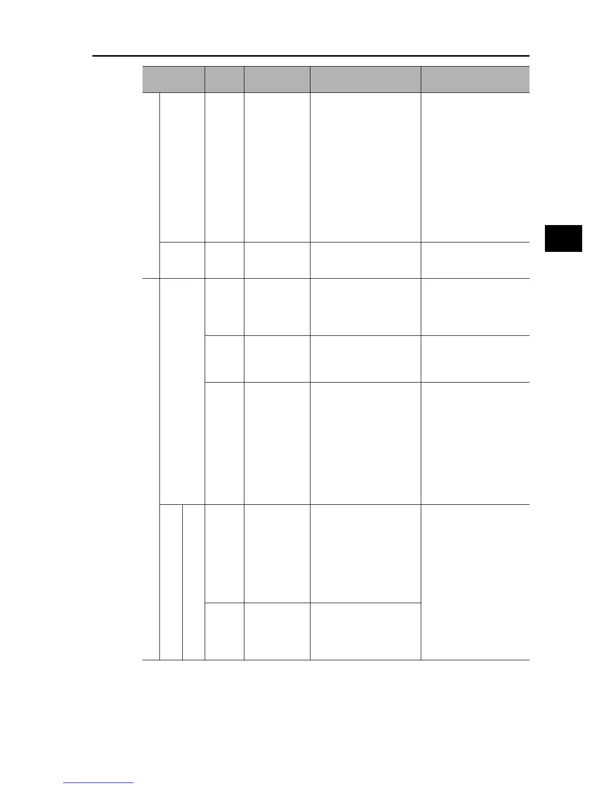
Terminal
symbol
Terminal name Description Specifications