6-26
6-7 Co-Inverter Communication
SYSDRIVE MX2 Series USER'S MANUAL (3G3MX2-Axxxx)
6
Communication Function
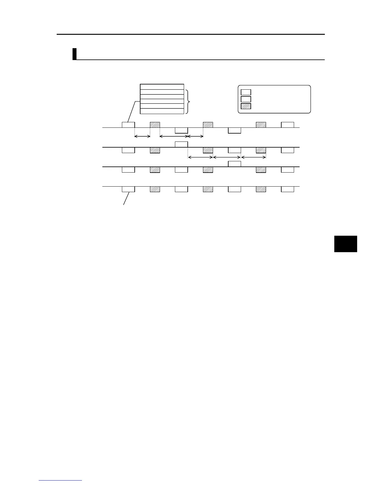
Example of Inverter-Inverter Communication Sequence
Shown below is a communication sequence involving a total of four Inverters from station
numbers 01 to 04, where the Master Inverter is one of 01 to 03.
For the Management Inverter, be sure to set a value other than 0 (1 s or more is recommended)
in Communication Error Timeout Time (C077). When 0 is set, the Co-inverter communication
function will stop if the data sent from the Master Inverter cannot be received.If the function has
stopped, reconnect the Management Inverter or perform a reset (by turning the RS terminal ON
and then turning it OFF).
The communication timeout timer starts counting when the recipient starts waiting for data. If data
reception is not completed within the set time, a timeout occurs (t3 in the above figure) and the
operation specified by Operation Selection on Communication Error (C076) takes place.
If the Management Inverter is the master, the master switching command is sent after an elapse
of the silent interval + Communication Wait Time (C078) following the sending of data by the
Master Inverter (t1 in the figure above).
If an Inverter other than the Management Inverter is the master, the master switching command
is sent after an elapse of the silent interval + Communication Wait Time (C078) following the
receiving of data from the Master Inverter (t2 in the figure above).
If "01: Always started" is selected for Co-inverter Communication Start Selection, the Management
Inverter starts sending the moment the power is turned on. Accordingly, any delay in the power-
on timing of other Inverter prevents normal communication and the Management Inverter
experiences a communication timeout. If "Always started" is selected, confirm starting of all other
Inverters and then start the Management Inverter at the end.
Do not set 08FFh (EEPROM write) or 0901h (EEPROM write mode selection) in the recipient
register.
If any one of C096 to C100 is changed, the change will not be reflected until the power is
reconnected or a reset is performed (by turning the RS terminal ON and then turning it OFF).
Management
Inverter (01)
Inverter (02)
Inverter (03)
Inverter (04)
Send
Receive
Send
Receive
Send
Receive
Send
Receive
M
S
S
S
M
S
S
S
M
S
S
S
M
S
S
S
Station register data
02 xxxx xxxx
02 xxxx xxxx
03 xxxx xxxx
03 xxxx xxxx
Up to five recipients
can be specified.
t3 t2
t3 t3
All slaves receive data from the master,
but they will discard the data
if the data is not addressed to themselves.
t1: Silent interval + Communication Wait Time (C078)
t2: Silent interval + Communication Wait Time (C078)
t3: Communication Timeout Time (C077)
t1
M
Sent data from the master
S
Received data in the slave
Master switching command
t3

 Loading...


