Compax3 device description
C3I10T10
192-120100 N16 C3I10T10 - December 2010
Emergency stop and protective door monitoring without external
safety switching device.
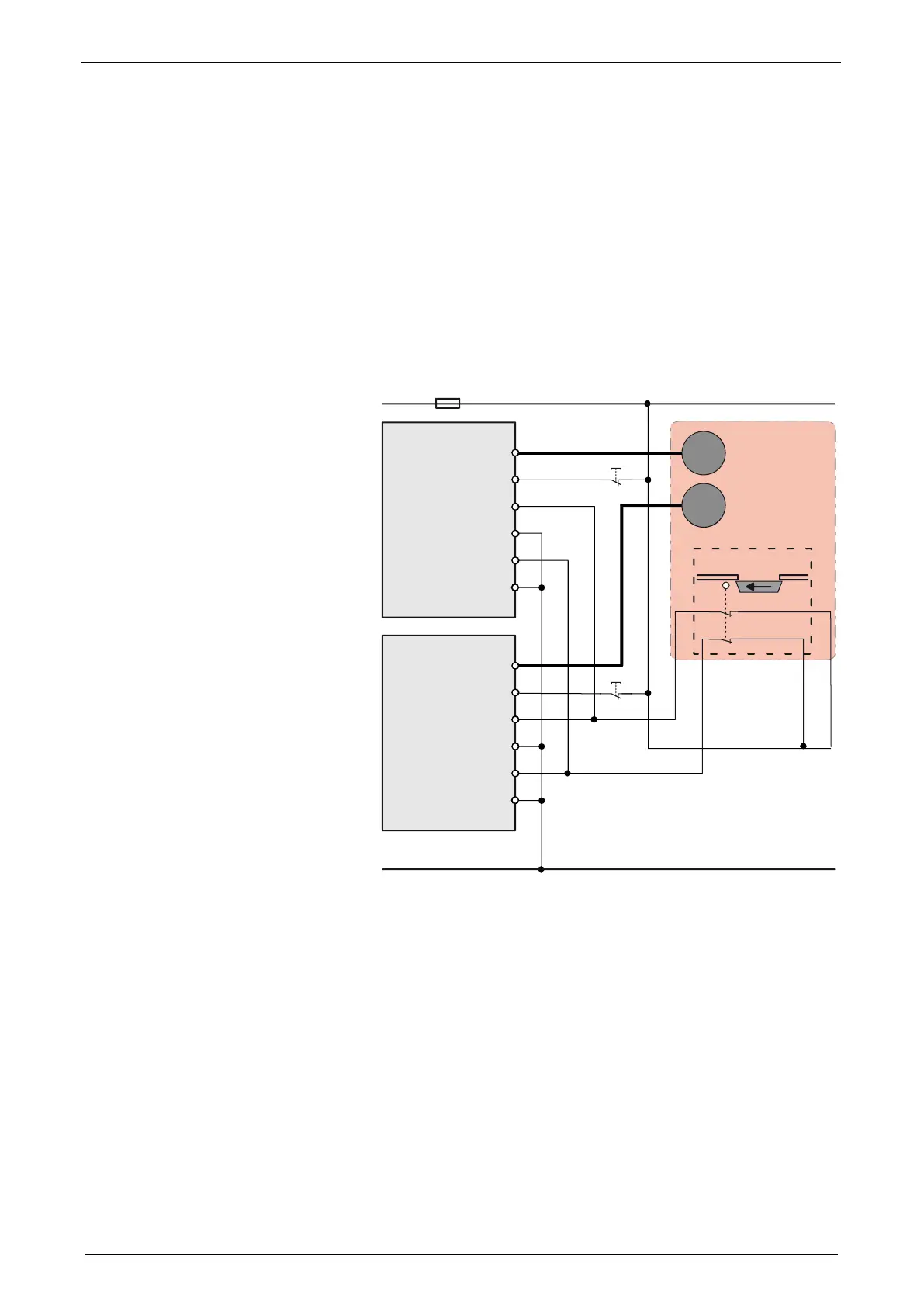
With Compax3M, a 2-channel protective door monitoring switch or a 2 channel
emergency power-off switch can be directly connected. The figure below visualizes
an application with 2 channel protective door monitoring switch.
The Compax3M drive modules with PSUPxx mains rectifier must be located in a
protected area (IP54 control cabinet). Outside this protected area, the line guiding
to the external switches must be separated channelwise or must be especially
protected (blinded).
It is also permitted to use one acknowledgement switch for both servo drives at a
time. In both cases the acknowledgement does only correspond to category B,
therefore this acknowledgement should not be used if there is any possibility of
stepping in the dangerous area. In this case, an external acknowledgement device
must be used.
GND24V
+24V
S1
S1
motor
motor
Safety door closed
Schutztür geschlossen
Danger Zone
Gefahrenbereich
S3
S4
X14.4
X14.3
X14.2
Energize
Compax3M
X3
X14.1
X14.4
X14.3
X14.2
Energize
Compax3M
X3
X14.1
STO-GND
STO2/
STO-GND
STO1/
STO-GND
STO2/
STO-GND
STO1/
 Loading...


