5.18
BODY / STEERING / SUSPENSION
9923523 - 2012 RANGER RZR 570 Service Manual
© Copyright 2011 Polaris Sales Inc.
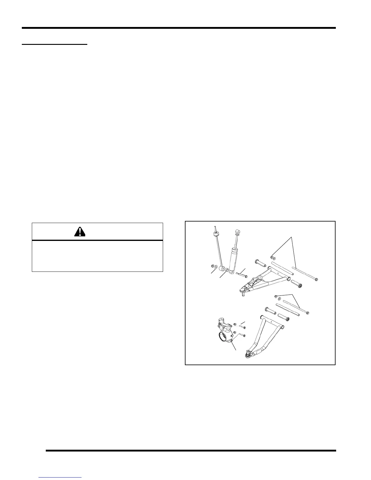
FRONT A-ARMS
Removal / Replacement
The following pro cedure details upper and lower A-arm
removal and replacement on one side of the vehicle.
1. Elevate and safely support the front of the vehicle and
r
emove the front wheel.
2. Remove lower shock fastener (A) from the upper A-
a
rm.
3. Remove upper ball joint pinch bolt (B) from bearing
carrier.
4. Using a soft face hammer, tap on bearing carrier to
lo
osen the upp er A- arm ba ll joint en d while lifting
upward on the upper A-arm. Completely remove the
ball joint end from the bearing carrier.
5. Remove the front bumper to allow
A-arm bolt removal.
6. Loosen an d remove th e u pper A-arm th rough-bolt
fastene
r ( C) a nd r emove the upper A-arm from the
vehicle.
7. Examine A-a rm b ushings and p ivot tube (see
“
Exploded View”). Replace if worn. Discard hardware.
8. If not replacing the A-arm, thoroughly clean the A-arm
a
nd pivot tube.
9. Install new ball joint into A
-arm. Refer to “Ball Joint
Replacement” section.
10. Insert new A-arm bushings and pivot tube into new A-
a
rm.
11. Install new upper A-arm assembly onto vehicle frame.
Torque
new bolt to specification.
12. Insert u pper A-arm ball jo int e nd into the b earing
carrier. Install
upper ball jo int pinch bolt (B) into the
bearing carrier and torque bolt to specification.
13. Attach shock to A-arm with spacer (D) or washer (G)
and
fa stener (A). To rque lowe r shock bolt to
specification.
14. Remove lower ball joint pinch bolt (E) from bearing
ca
rrier.
15. Using a soft face hammer, tap on bearing carrier to
loosen
the lower A-arm ball joint end while pushing
downward on the lower A-a rm. Com pletely r emove
the ball joint end from the bearing carrier.
16. Loosen an d re move the lower A-ar m thro ugh-bolt
fa
stener (F ) a nd re move the lo wer A-arm fr om the
vehicle.
17. Examine A-arm bushin gs and pivot tube (se e
“Explod
ed View”). Replace if worn. Discard hardware.
18. If not replacing the A-arm, thoroughly clean the A-arm
and pivot tube.
19. Install new ball j oint into A-a
rm. Refer to “Ball Joint
Replacement” section.
20. Insert new A-arm bushings and pivot tube into new A-
arm
.
21. Install new lower A-arm assembly onto vehicle frame.
Tor
que new bolt to specification.
The locking agent on the existing bolts was
destroyed during removal. DO NOT reuse old
hardware. Serious injury or death could result if
fasteners come loose during operation.
 Loading...