5.25
BODY / STEERING / SUSPENSION
5
9923523 - 2012 RANGER RZR 570 Service Manual
© Copyright 2011 Polaris Sales Inc.
Installation
1. Install lo wer A- arm as sembly o nto ve hicle f rame.
Torque new fasteners to specification.
2. Attach lower A-a rm to be aring carr ier. Torque ne w
fastene
r to specification.
3. Route brake line on top of th e lower A-arm and into
the routing
clip.
4. Reinstall the lower portion of the
shock and stabilizer
bar to the lower A-arm. Tor que sh ock fastener to
specification.
5. Install upper A-a rm a ssembly o nto vehicle frame.
To
rque new fastener to specification.
6. Attach upper A-arm to bearing carrier. Torque ne w
fastene
r to specification.
7. Install wheel and torque wheel nuts to specification.
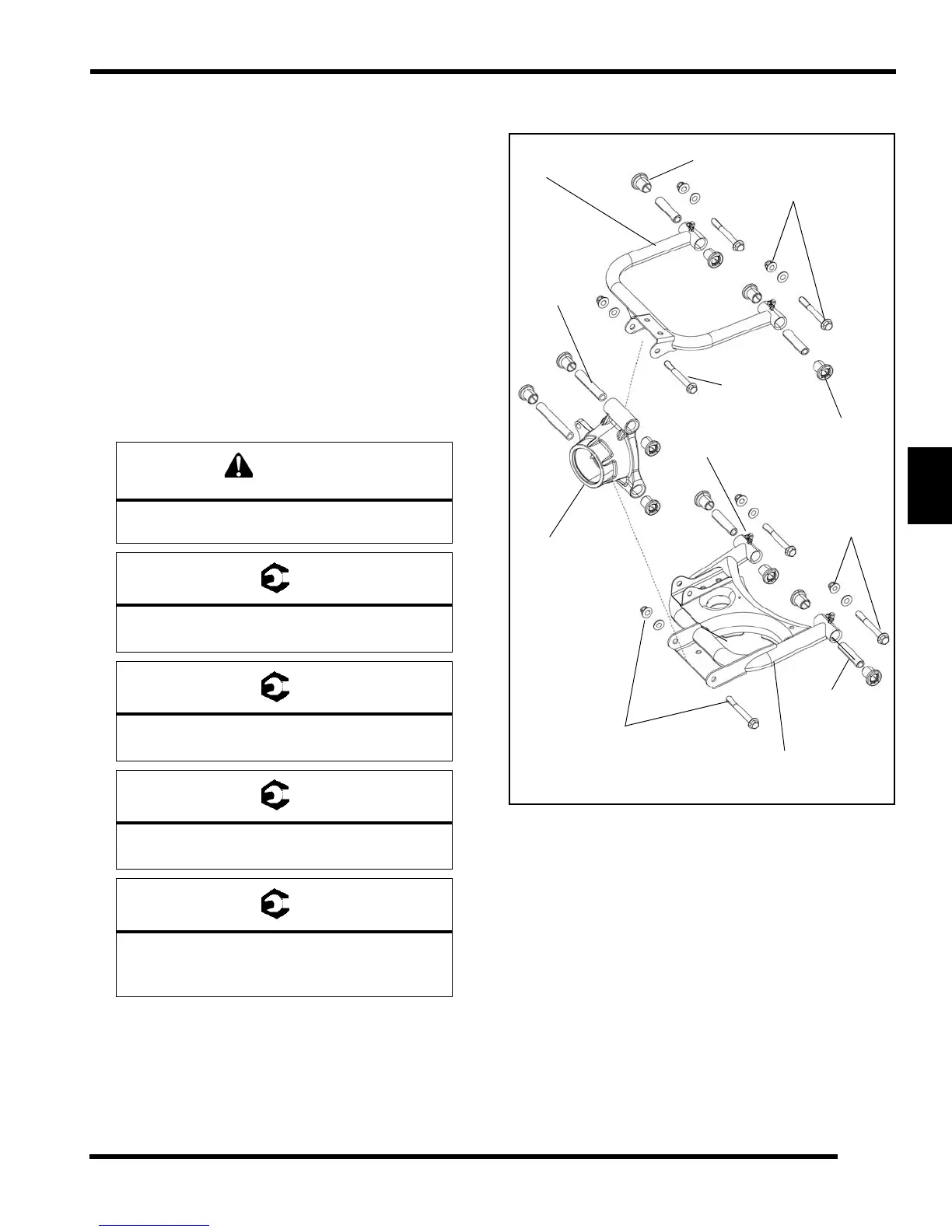
Exploded View
Upon A-arm installation completion, test vehicle
at low speeds before putting into service.
Rear Upper / Lower A-arm Bolts:
39 ft. lbs. (53 Nm)
Shock Mounting Bolts:
37 ft. lbs. (50 Nm)
Upper and Lower Bearing Carrier Bolts:
40 ft. lbs. (54 Nm)
Wheel Nuts:
Steel Wheels: 27 ft. lbs. (37 Nm)
Aluminum Wheels: 30 ft. lbs. + 90° (1/4 turn)
Upper
A-arm
Lower
A-arm
Bearing
Bushings
Pivot Tube
Carrier
Pivot
Grease
Zerk
Tube
Upper Fastener
Lower
Fastener
Lower
Fastener
Upper
Fastener
Bushings
 Loading...