10.24
ELECTRICAL
9923523 - 2012 RANGER RZR 570 Service Manual
© Copyright 2011 Polaris Sales Inc.
Charging System Stator (Alternator) Tests
Three test s can be pe rformed u sing a mu lti-meter to
determine the condition of the stator (alternator).
TEST 1: Resistance Value of Each Stator Leg
1. Measure the r esistance valu e of e ach o f the thr ee
stator
legs: Y1 to Y2, Y1 to Y3, and Y2 to Y3. Each
test should measure: 0.2 Ohms ± 15%
NOTE: If there are any significant variations in oh m
re
adings b etween t he three legs it is a n indic ation
that one of the stator legs may be weak or failed.
TEST 2: Re sistance Value of Eac h S tator Leg to
Ground
1. Measure the r esistance valu e
of each of the stator
legs to gr ound: Y1 to Ground, Y2 to Ground, Y3 to
Ground.
Each test should measure: Ope
n Line (OL)
NOTE: Any meas urement ot her than Inf inity ( open)
will
indicate a failed or shorted stator leg.
TEST 3: Measure AC Voltage Output of Each Stator
Leg at
Charging RPM
1. Set the selector dial to measure AC Voltage.
2. Start the engine and let it idle.
3. While hold ing the eng ine at a specified RPM,
se
parately measure the voltage across each ‘leg’ of
the stator by connecting the meter leads to the wires
leading from the alternator (Y1 to Y2, Y1 to Y3, Y2 to
Y3).
4. Refer to the fo llowing table for approximate AC
Vo
ltage readings according to RPM. Test each leg at
the specified RPM in the table.
Example: The alt ernator cu rrent ou tput reading
sh
ould b e approximately 21 VAC at 1300 RPM
between each ‘leg’.
NOTE: If one or more of the st ator leg output AC
volta
ge varies significantly from the specified value,
the stator may need to be replaced.
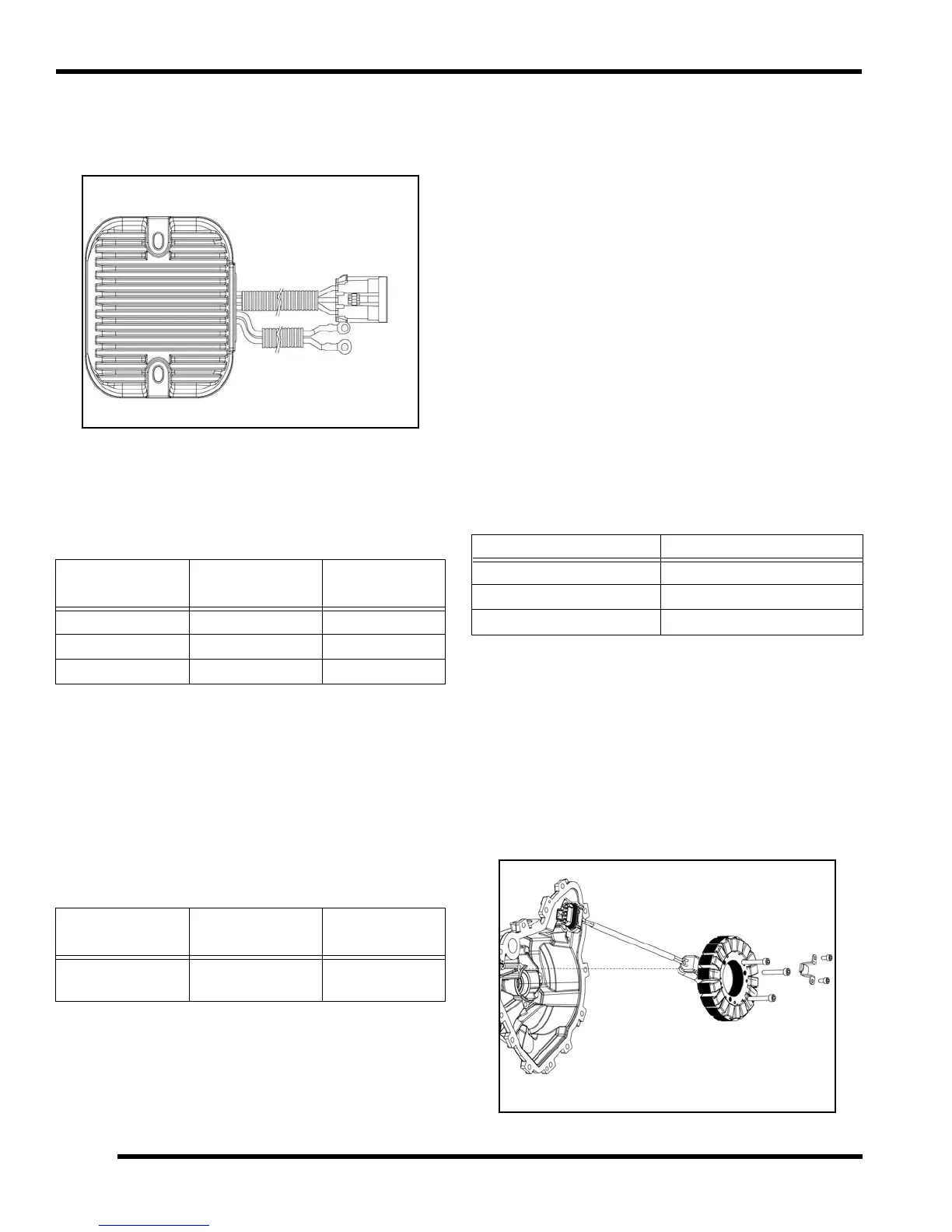
Stator (Alternator) Replacement
Refer to Chapter 3 (Engine / Cooling System) to service
the stator.
NOTE: The stator co ver ca n be remo ved with th e
engine
installed in the chassis.
IMPORTANT: Be sure to thoroughly drain the engine
coolan
t and clea n the are a around the st ator cover
prior to removal. See chapter 3.
Test
Connect Meter
Lea
ds To:
Ohms Reading
Battery Charge Coil Y1 to Y2 0.2 ± 15%
Battery Charge Coil Y1 to Y3 0.2 ± 15%
Battery Charge Coil Y2 to Y3 0.2 ± 15%
Test
Connect Meter
Lea
ds To:
Ohms Reading
Battery Charge
Co
il
Y1, Y2, or Y3
to Ground
Open Line
(Infinity)
RPM Reading AC Voltage (VAC) Reading
1300 22 VAC ± 25%
3000 51 VAC ± 25%
5000 85 VAC ± 25%

 Loading...