10.17
ELECTRICAL
10
9923523 - 2012 RANGER RZR 570 Service Manual
© Copyright 2011 Polaris Sales Inc.
Instrument Cluster Installation
1. Spray a soap an d water mixtur e o nto th e o uter
surface area of the instrument cluster. This will help
the instrument cluster slid e into the r ubber mount
more easily.
2. Be sur e the r ubber mou nt inside the dash is fu lly
in
stalled a nd that the ind exing key on the ru bber
mount is lined up with the keyway in the dash.
3. Hold the das h securely and
inse rt the in strument
cluster into the dash. Twist the instru ment cluster
gently in a c lockwise moti on to p roperly seat the
instrument cluste r into the r ubber mo unt. App ly
pressure on th e b ezel wh ile pr essing do wn on th e
instrument cluster.
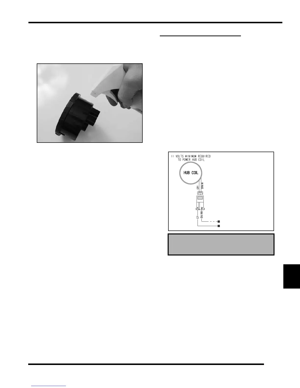
ALL WHEEL DRIVE COIL
Operation Overview
• When the AWD switch is “ON”, 12 VDC power is
present at the hub coil.
• If the criteria is met, the E
ngine Controller provides
a ground path (brown/white wire). When this
occurs the AWD icon should display in the
instrument cluster.
• The AWD system must be grounded to operate.
Diagnosing System Failures
• Verify the AWD switch is functional and that a
minimum of 11 volts is present at the hub coil.
• Verify the AWD hub coil is functional. Test the
A
WD hub coil using an ohm meter. See
specifications below:
• Verify the wiring harness, wiring, connectors,
conn
ector pins and grounds are undamaged,
clean and connect properly.
• Verify continuity of wire co
nnections with a known
good volt/ohm meter.
IMPORTANT: Verify all wire
s and wiring connections
have be en tested properly wit h a k nown go od v olt/
ohm mete r bef ore suspecting a co mponent f ailure.
80% of all electrical issues are caused by bad/failed
connections and grounds.
AWD Hub Coil Resistance:
24 Ohms ± 5%
Test Resistance Test Resistance
Readings should be: Readings should be:
GY to BN/WH: ~ 24 OhmsGY to BN/WH: ~ 24 Ohms
GY to Ground: No ConnectionGY to Ground: No Connection

 Loading...