2.19
MAINTENANCE
2
9923523 - RANGER RZR 570 Service Manual
© Copyright 2011 Polaris Sales Inc.
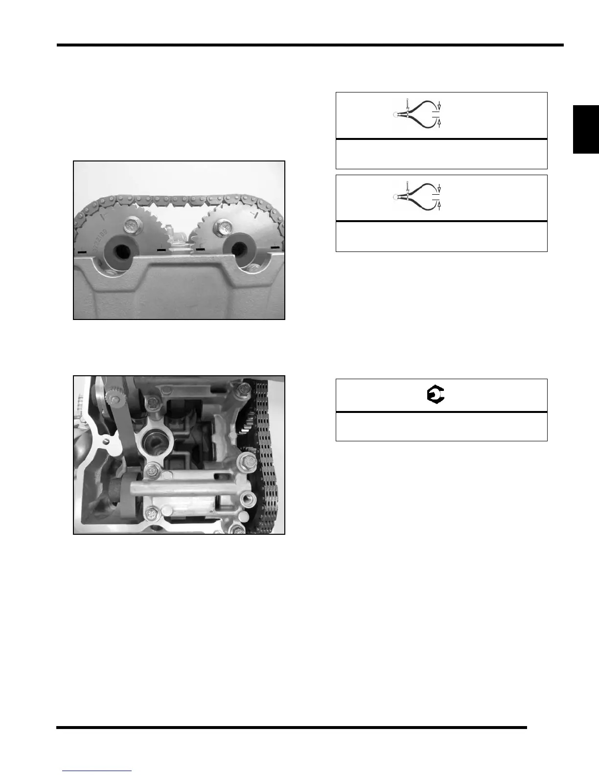
7. Rotate th e drive clu tch co unter-clockwise until the
cam chain sprocket timing marks are aligned with the
gasket sur face as sho wn (see Ch apter 3 for mo re
TDC setting procedures).
IMPORTANT: Intake ca m s procket sh ould ha ve “I”
mar
ks
aligned with ga sket surface a nd the ex haust
cam spr ocket shou ld hav e “E” ma rks aligned with
gasket surface.
8. Measure the valve clearance of each valve using
a
thickness (feeler) gauge. Record the measurement if
clearance is out of specification.
9. If the valve clearance is out o
f specification, proceed
to “Valve Clearance Adjustment” (see Chapter 3).
10. Repeat steps 8- 9 u ntil all (4) valves h ave b een
in
spected.
11. Inspect the valve cover seal and replace if necessary.
12. Install the valve cover and spark plug as outlined in
Chapter
3.
13. Install d rive b elt an d o uter clu tch cover a nd ( 8)
re
taining screws (see Chapter 6)
14. Connect the negative (-) battery cable to the battery.
15. Start the engine to ensure proper operation.
16. Reinstall the cargo box access panel and seats (see
Chapter
5).
I
I
E
E
Image for Reference Only
= In. / mm.
Intake Valve Clearance (cold):
.005-.007 in. (0.125-0.175 mm)
= In. / mm.
Exhaust Valve Clearance (cold):
.008-.010 in. (0.152-0.254 mm)
= T
Outer Clutch Cover Screws:
45-50 in. lbs. (5 Nm)
 Loading...