106 PI-MAX
®
4 System Manual Issue 9
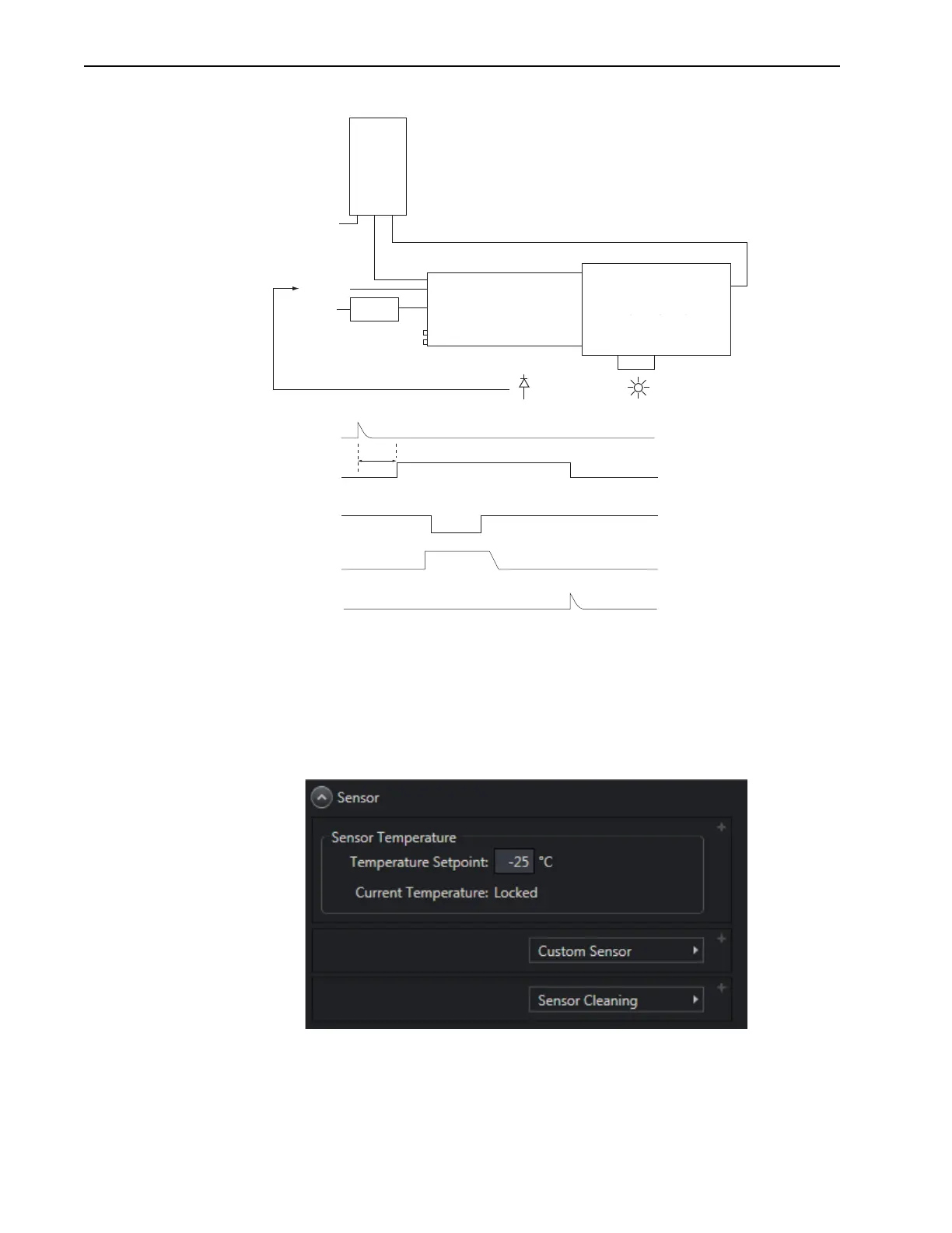
Figure 6-4: Block/Timing Diagram: Swept Gate Experiment
2.
Turn on all equipment and launch LightField.
3. Open the Sensor expander and configure the camera’s temperature, in degrees Celsius,
by entering the desired
Temperature Setpoint. See Figure 6-5.
Figure 6-5: Typical Sensor Expander
Computer
110/220
96 – 264
Trigger In
GigE
Power
Supply
PI-MAX4
USB
Spectrograph
Photodiode
Photocathode Gating
Off
~12 nS
On
Off
Off
On
Off
MCP Gating
AUX Out
* Level changes for T
0
depend on the pulse sequence(s) defined by the user.
Delay is programmable
MCP Gating
Photocathode Gating
T
0
remains high for the duration
of the pulse ensemble *
Trigger In
T
0