188 PI-MAX
®
4 System Manual Issue 9
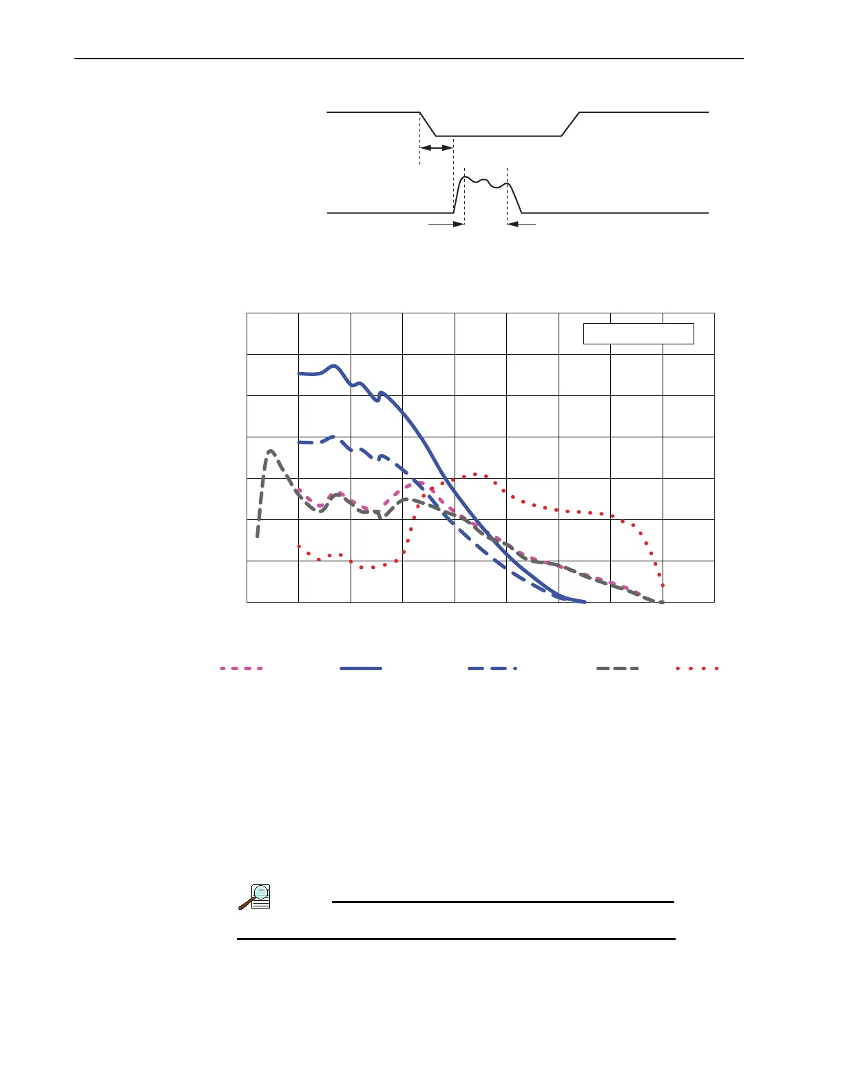
Figure 11-3: Timing Diagram: MCP Gated Operation for Gen II Intensifiers
Figure 11-4: QE Curves: Gen II Intensifiers
11.1 Setup and Operation
The PI-MAX4 must have an installed MCP Gating board.
• Make all of the required cable connections for the experiment.
• Apply power to the equipment and launch the application software.
• Configure the gating parameters. Start with a relatively long gate to acquire the
phenomenon of interest.
• Begin running the experiment.
• Finally, narrow down the gate to the desired operation.
Pulse repetition rate is limited to 8 kHz.
Photocathode Gating
(Slow Gate Intensifier)
MCP Gating
Effective Gate Width
~50 – 175 nS*
OFF
OFF
OFF
OFF
ON
ON
* Lead time is tube-dependent and is individually calibrated at the factory.
0
5
10
15
20
25
30
35
100 200 300 400 500 600 700 800 900 1000
YƵĂŶƚƵŵĸĐŝĞŶĐLJ;йͿ
WĂǀĞůĞŶŐƚŚ;ŶŵͿ
'ĞŶ///ŶƚĞŶƐŝĮĞƌƐ
RB Fast Gate
SRUV^&ĂƐƚ'ĂƚĞ^^ůŽǁ'ĂƚĞ