Chapter 8 Timing Generator 155
8.2.1 Supported Timing Generator Trigger Modes
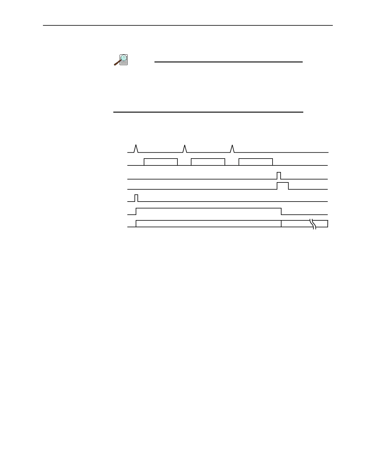
Trigger per Pulse: Each pulse of the single sequence is initiated by its own trigger.
All triggers must be:
• Generated from the same source, and
• Must all be either an internal or an external trigger. The
use of a combination of internal and external triggers is
not supported.
See Figure 8-4.
Figure 8-4: Timing Diagram: 3 Repetition Sequence, Trigger per Pulse
Supported Trigger Sources are:
• Source 1: Timing Generator internal trigger
Each pulse set of the sequence is initiated by the timing generator’s internal trigger.
• Source 2: External Trigger (on TRIGGER IN BNC)
Each pulse set is initiated by an external trigger.
8.3 Time Stamping
Time Stamping provides the ability to include the following timing data with each frame of
acquired data:
• Exposure Started;
This time stamp indicates the time control is passed from the camera FPGA to the
timing generator, not the actual image intensifier gate time.
Once control is passed to the timing generator, the timing generator waits for a
trigger or triggers (internal or external, as configured by the user.) The timing
generator then executes the timing the user has selected.
When the timing generator completes its task(s), control is then returned to the
camera FPGA.
• Exposure Ended.
This time stamp indicates the time when the timing generator returns control to the
camera FPGA.
The resolution for PI-MAX4 time stamps is 1 S.
TRIGGER
PULSES
EXPOSE
CCD
EXPOSE
PULSE SET PULSE SET PULSE SET
READOUT
TG_DONE
SEQ_DONE
AUX I/O