Chapter 2 System Installation 31
2.1 System Configuration Diagrams
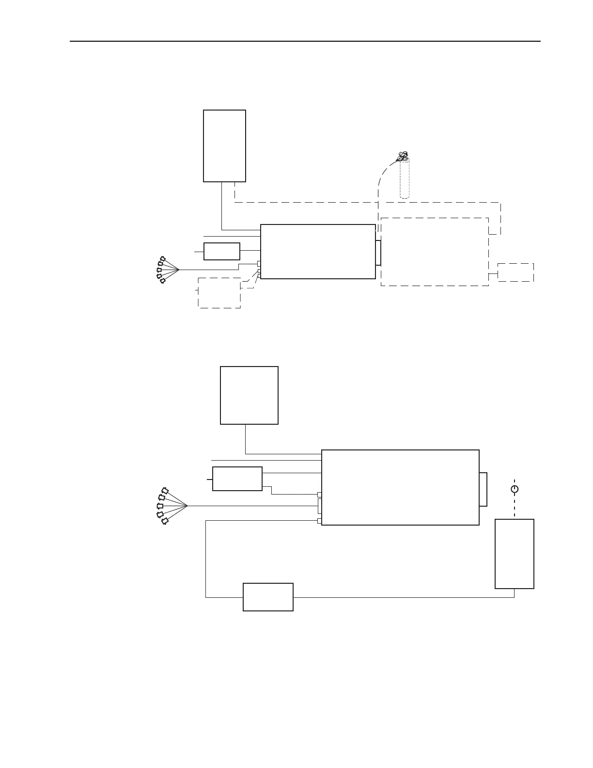
This section provides block diagrams of typical system configurations.
Figure 2-1: Typical PI-MAX4 System Diagram
Figure 2-2: Typical PI-MAX4: 1024i-RF System Diagram
CoolCUBE II
Coolant
Circulator*
* Spectrograph, coolant circulator, and dry nitrogen tank connections are optional.
90-264
100-240
Power
Supply
Power
Supply
Spectrograph
Acton SP2300i*
PI-MAX4
USB
Computer
Trigger In
GigE
Dry Nitrogen Tank
AUX I/O Cable
LASER
Modulator
100-240
GiGE
Trigger In
Power
Supply
PI-MAX4: 1024i-RF
Computer
USER RF OUT
LASER
POWER
AUX
POWER
AUX I/O Cable
4411-0097_0113
SPECTROGRAPH, COOLANT CIRCULATOR, AND DRY NITROGEN TANK CONNECTIONS
ARE
OPTIONAL AND ARE NOT SHOWN IN THIS DIAGRAM.