Chapter 9 LightField and Dual Image Feature 169
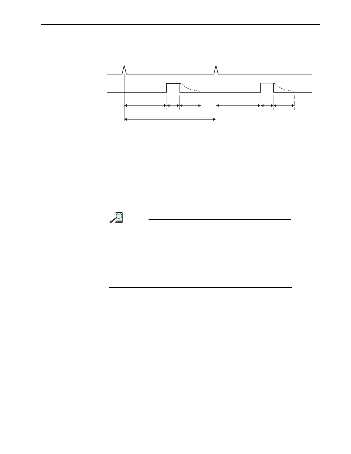
Figure 9-16 illustrates the timing diagram for a dual-trigger DIF acquisition.
Figure 9-16: Timing Diagram: Dual-Trigger DIF Acquisition
Perform the following procedure to configure a dual-trigger DIF acquisition:
1. The PI-MAX4 camera must be aligned and focused on the area of interest for this
experiment. This is best accomplished while the PI-MAX4 is operating in
Full Frame
readout mode (i.e., before switching to
DIF mode on the Readout expander.)
Verify that the
Phosphor Decay Delay is appropriate to the phosphor used by the camera.
The
Phosphor Decay Delay time entered in LightField can be viewed or changed by
clicking on the
Advanced button within the Common Acquisition Settings expander.
The Phosphor Decay Delay setting tells LightField how long
to wait following the gate pulse before shifting the image. If
there is some residual image from the first frame in the second
frame, simply increase the
Phosphor Decay Delay setting to
allow more time for the phosphor emission to decay before
shifting the image. If residual image is not an issue, then the
Phosphor Decay Delay setting can be decreased to reduce the
time between the two DIF images.
2. After the alignment and focus, the PI-MAX4 system needs to be placed into DIF mode.
• On the Readout expander, select DIF as the Mode.
• On the Common Acquisitions Settings expander, configure the Frames to Save
to a multiple of 2 (i.e., 2, 4, 6, etc.)
3. On the Trigger expander, verify that Trigger Response is set to Shift Per Trigger.
D1 W1 PD D2
SHIFT
BEHIND
MASK
TT
TRIGGER
W2 PD
SECOND FRAMEFIRST FRAME
IMAGES
',QLWLDO*DWH'HOD\PS)
PD: Phosphor Decay Time
W1: Pulse 1 Gate Width
777LPHEHWZHHQ7ULJJHUV':3'
D2: Pulse 2 Gate Delay
PLQLPXPFDPHUDGHOD\aQ6
W2: Pulse 2 Gate Width