272 PI-MAX
®
4 System Manual Issue 9
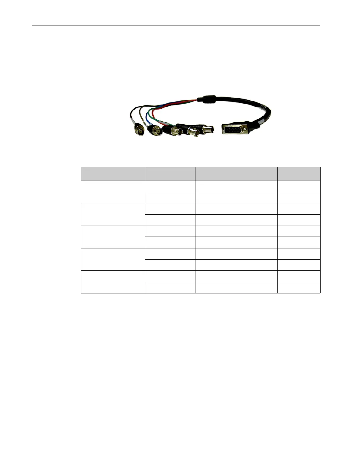
A.6.1 AUX I/O Cable
Each PI-MAX4 system includes an AUX I/O cable that provides convenient access to
several system signals. The AUX I/O interface cable is comprised of a male DB26
connector on one end, and five female BNC cables on the other end, each of which provides
access to a system signal.
Figure A-2 illustrates a typical cable.
Figure A-2: AUX I/O Interface Cable (Part Number 6050-0660)
Table A-7 provides the color code and pinout information for the AUX I/O interface cable.
Table A-7: AUX I/O Interface Cable Pinout and Signal Information
Cable Color BNC Conductor Signal Name DB26 Pin #
Red Center T0 OUT 1
Shield Ground 3
Green Center PRE-TRIG IN 2
Shield Ground 6
Blue Center SyncMASTER1 7
Shield Ground 18
Gray Center GP INPUT 0 8
Shield Ground 20
Black Center SyncMASTER2 23
Shield Ground 25