214 PI-MAX
®
4 System Manual Issue 9
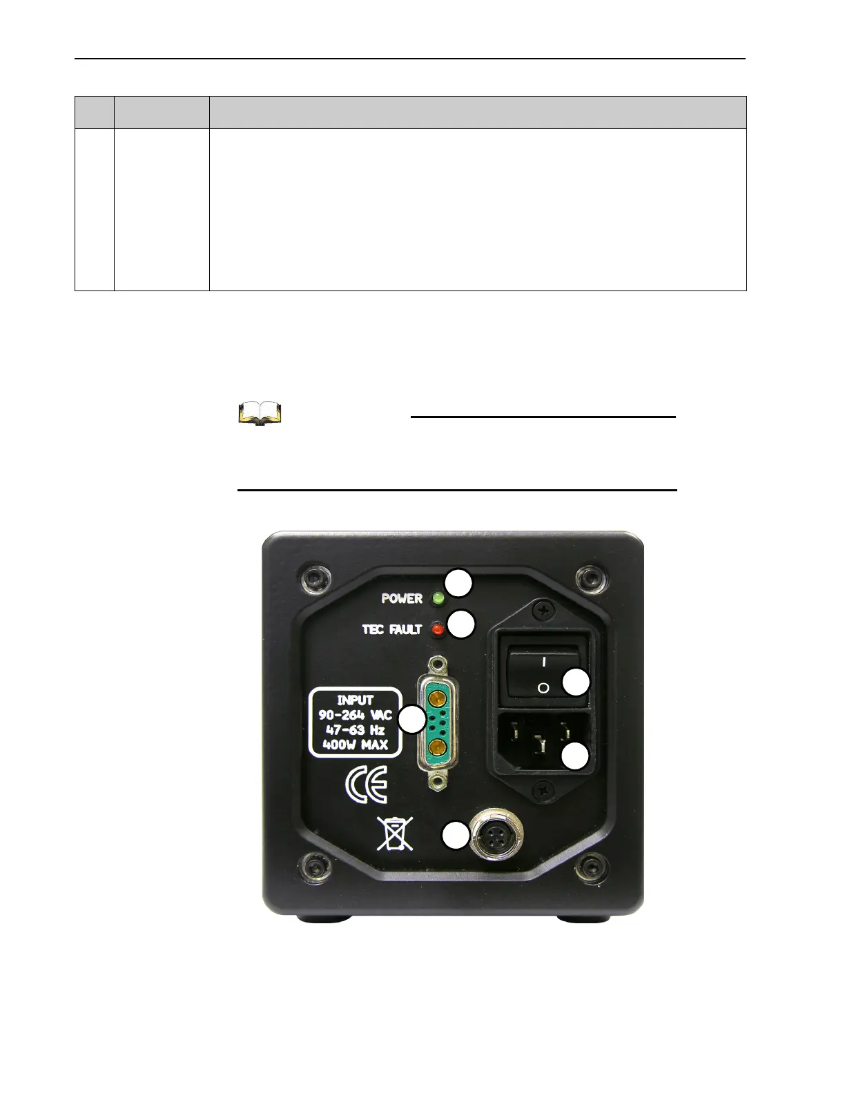
13.4.1 PI-MAX4: 1024i-RF Power Supply Rear Panel Information
The rear panel of the PI-MAX4: 1024i-RF Power Supply is illustrated in Figure 13-14 with
connectors, indicators, and switches identified. Refer to Table 13-3 for complete
descriptions and information.
Refer to Section 13.4, PI-MAX4: 1024i-RF Rear Panel
Information, on page 212 for corresponding information about
the PI-MAX4: 1024i-RF camera.
Figure 13-14:PI-MAX4: 1024i-RF Power Supply Rear Panel
13 AUX I/O 26-pin male DB connector. Provides five I/O signals that can be used to input a trigger to initiate data
acquisition, monitor frame readout status, and/or control an external shutter.
The five I/O signals are:
• T0 Out;
• Pre-Trigger In;
• SyncMASTER1;
• General Purpose Input 0;
• SyncMASTER2.
Refer to Section A.6, AUX I/O Interface, on page 270, for additional information.
Table 13-2: PI-MAX4: 1024i-RF Connectors, Indicators, and Switches (Sheet 2 of 2)
# Label Description