160 PI-MAX
®
4 System Manual Issue 9
• Shift Per Trigger
Two triggers are used to acquire the two images (i.e., one trigger per image.)
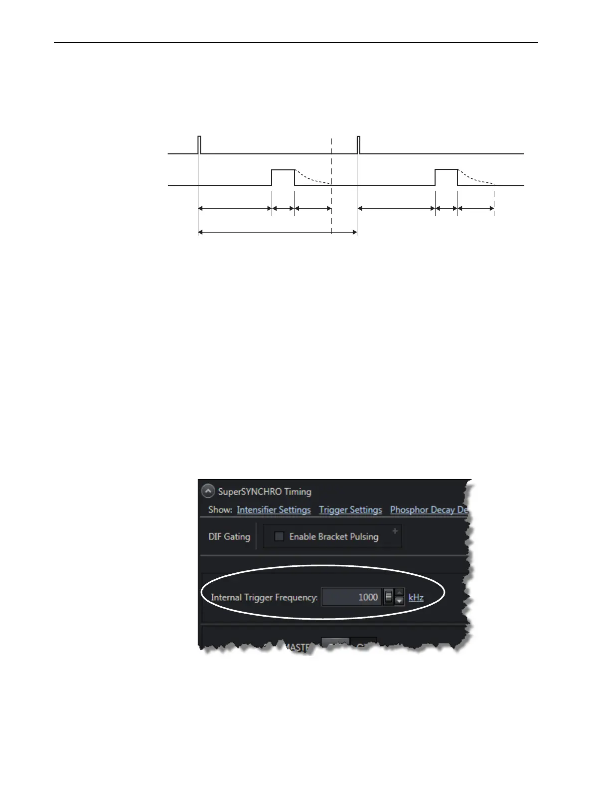
Figure 9-5 illustrates the timing diagram for a dual-trigger DIF acquisition.
Figure 9-5: Timing Diagram: Dual-Trigger (Shift Per Trigger) DIF
9.3.2 Trigger Source
Trigger(s) can either be internally generated by the PI-MAX4 or can be generated by an
external source connected to the
TRIGGER IN connector on the rear of the camera.
Valid values for
Trigger Source are:
• Internal;
• External.
9.3.2.1 Internal Trigger Source
Trigger pulses are generated by the PI-MAX4 using the configured
Internal Trigger
Frequency
on the SuperSYNCHRO Timing expander. See Figure 9-6.
Figure 9-6: SuperSYNCHRO Timing Expander: DIF Operation
The range of valid frequencies is 1 Hz to 1 MHz, in 1 Hz increments.
The
Internal Trigger Frequency setting also determines the frequency of SyncMASTER1
and
SyncMASTER2 outputs.
D1 W1 PD D2
SHIFT
BEHIND
MASK
TT
TRIGGER
W2 PD
SECOND FRAMEFIRST FRAME
IMAGES
',QLWLDO*DWH'HOD\PS)
PD: Phosphor Decay Time
W1: Pulse 1 Gate Width
777LPHEHWZHHQ7ULJJHUV':3'
D2: Pulse 2 Gate Delay
PLQLPXPFDPHUDGHOD\aQ6
W2: Pulse 2 Gate Width