168 PI-MAX
®
4 System Manual Issue 9
d. Configure the following AUX Output Trigger parameters as required:
• AUX Output Delay;
• AUX Output Width.
e. To enable trigger outputs on the AUX I/O cable’s SyncMASTER1 and
SyncMASTER2 connectors, click on the SyncMASTER: ON button.
When
SyncMASTER is enabled, the output of the SyncMASTER1 connector is
driven at the frequency specified by the
Internal Trigger Frequency.
The
SyncMASTER2 frequency is also specified by the Internal Trigger
Frequency
, but can be delayed from 0 ns to 999,700 ns, in 100 ns increments.
5. Verify that the I.I.T. power switch on the rear of the PI-MAX4 is in the ON position, and
that
Enable Intensifier has been checked on the Common Acquisition Settings
expander.
6. When ready, click Acquire to start image acquisition.
9.6 Configure a Dual-Trigger DIF Acquisition
The operation of a PI-MAX4 in DIF mode is similar to the standard operation of a
PI-MAX4 with
SuperSYNCHRO Timing. This section describes the minor operational
differences that are due to the special timing modes required for DIF.
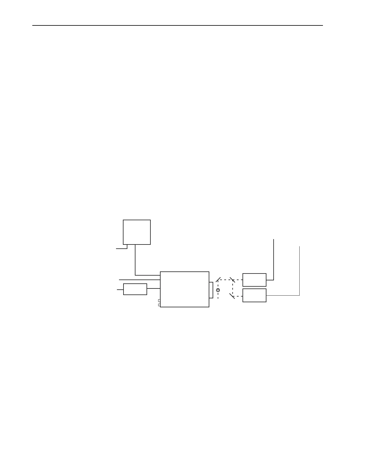
Figure 9-15 is a block diagram of the typical equipment configuration for a dual-trigger DIF
acquisition.
Figure 9-15: Block Diagram: Dual-Trigger DIF Acquisition
LASER 1
LASER 2
Trigger 1
Trigger 2
100-240
100-240
GiGE
Trigger In
Power
Supply
PI-MAX4
Computer
4411-0139_0090
* SPECTROGRAPH, COOLANT CIRCULATOR, AND DRY NITROGEN TANK CONNECTIONS ARE OPTIONAL