Chapter 5 Gate Mode Operation 73
Figure 5-8: Step 3: Non-Overlapped, Transfer to Output Node
4.
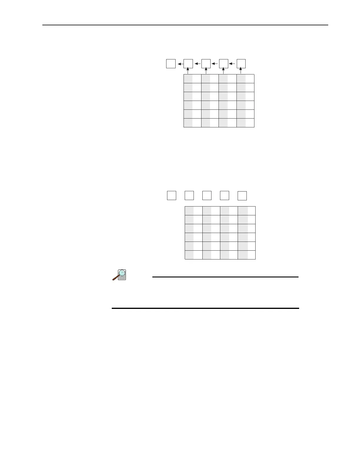
Figure 5-9 illustrates the end of the readout. Both the imaging and storage areas
are empty. When the intensifier is gated on again, signal charge will again be
accumulated.
Figure 5-9: Step 4: Non-Overlapped, End of Readout
A subsection of the CCD can be read out at full resolution,
sometimes increasing the readout rate while retaining the
highest resolution in the region of interest (ROI.)
3
Charge from first pixel has been
shifted to the Output Node.
A1 B1
C1
A2 B2
A4
A3
B4
B3
A6
A5
B6
B5
C2
C4
C3
C
6
C5
D2
D4
D3
D6
D5
D1
4
After first image is read out, masked areas
are empty. Second exposure begins if in Freerun
mode. Otherwise, waits for Ext Sync.