84 PI-MAX
®
4 System Manual Issue 9
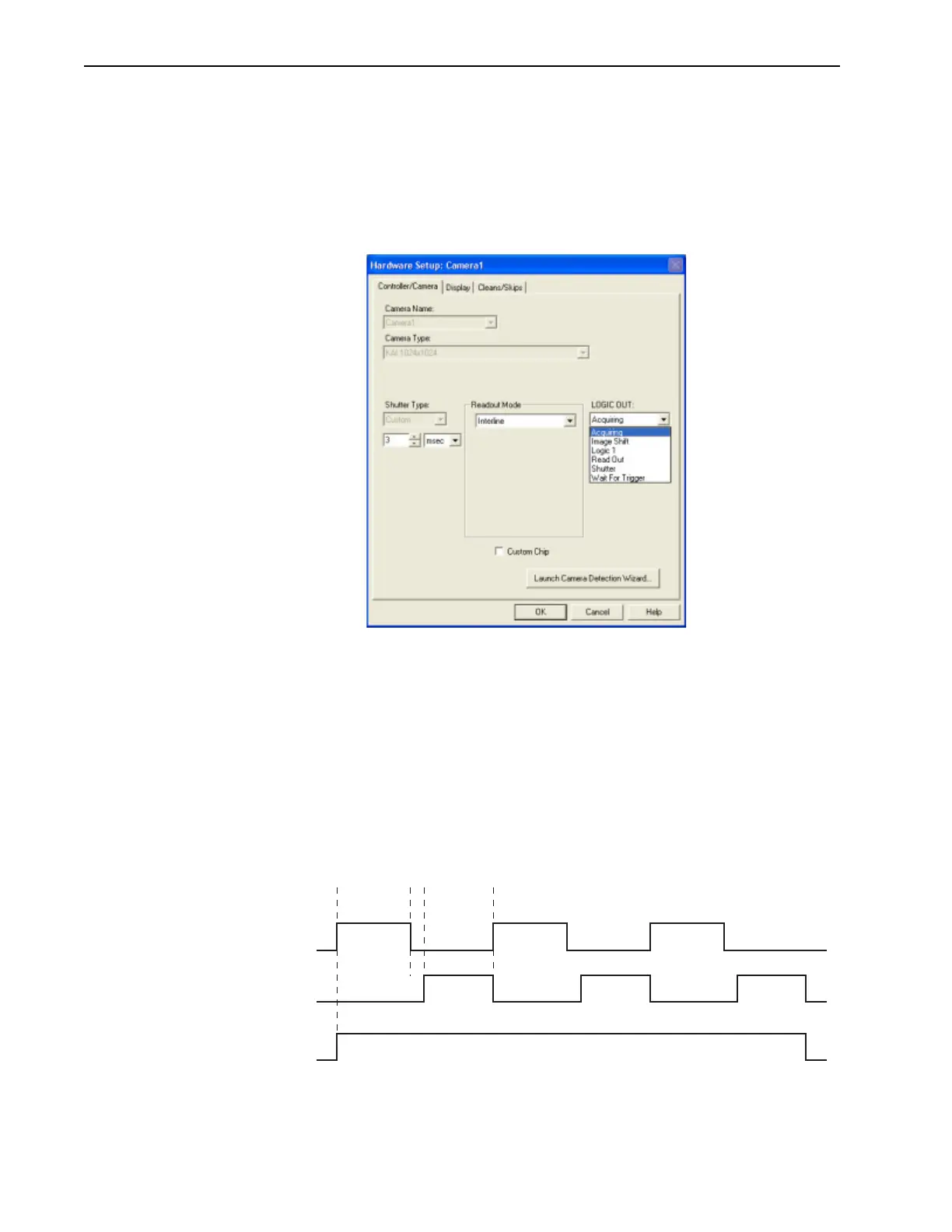
5.12 Logic Out Control
The TTL-compatible logic level output (0 to +3.3 V) from the LOGIC OUT connector on
the rear panel can be used to monitor camera status and control external devices. By
default, the logic output level is high while the action is occurring. The timing of the level
changes depends on the output type selected on the
Setup —> Hardware —> Controller/
Camera
tab {Trigger expander}. See Figure 5-18.
Figure 5-18: Typical PI-MAX4 Hardware Setup Dialog
Valid configuration settings for LOGIC OUT are:
• Acquiring {Acquiring}
After a start acquisition command, this output changes state on completion of the
array cleaning cycles that precede the first exposure. Initially low, it goes high to
mark the beginning of the first exposure. In Focus mode operation it remains high
until the system is halted. If a specific number of frames have been programmed, it
remains high until all have been taken and then returns low. Figure 5-19 assumes
three frames have been programmed.
Figure 5-19: Timing Diagram: Shutter {Shutter Open}, Read Out {Reading Out},
Acquiring {Acquiring}
{Acquiring}
Open Close Open Close Open Close
Shutter
{Shutter Open}
Read Read Read
Read Out
{Reading Out}
(Data
transferred)
(Data
transferred)
(Data
transferred)
t
exp
t
R
t
c