250 PI-MAX
®
4 System Manual Issue 9
16.2 Switches, Connectors, and Indicators
This section provides information about the switches, connectors, and indicators found on
the PI-MAX4 family of cameras.
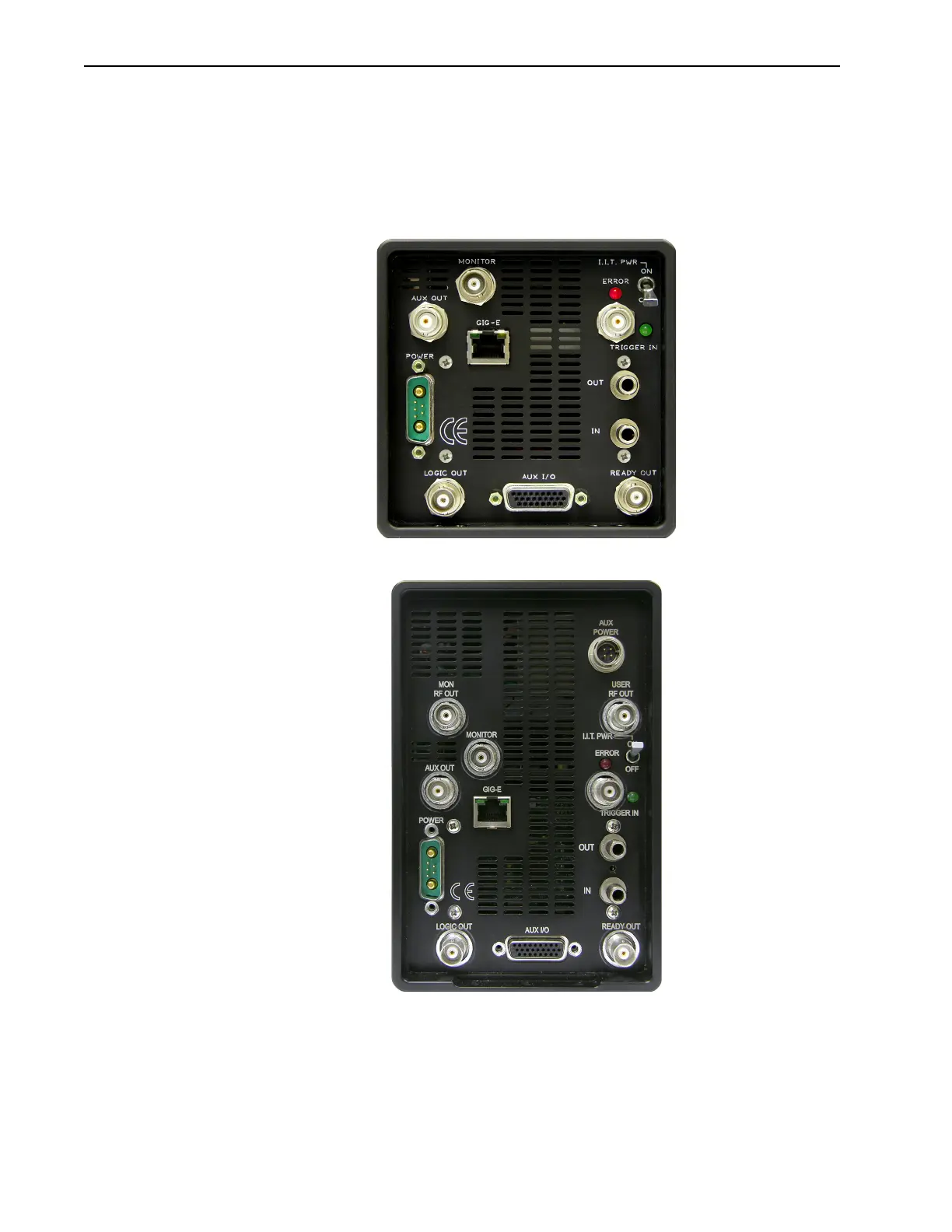
• Figure 16-1 shows the typical PI-MAX4 Rear Panel;
• Figure 16-2 shows the PI-MAX4: 1024i-RF Rear Panel.
Figure 16-1: PI-MAX4 Rear Panel
Figure 16-2: PI-MAX4: 1024i-RF Rear Panel
Rear panel switches, connectors, and indicators are presented in alphabetical order.
• When a switch, connector, or indicator is unique to the PI-MAX4: 1024i-RF, its
description will specify PI-MAX4: 1024i-RF.
• Similarly, when a switch, connector, or indicator is unique to the PI-MAX4:EM, its
description will specify PI-MAX4:EM.
 Loading...

