72 PI-MAX
®
4 System Manual Issue 9
Figure 5-6: Step 1: Non-Overlapped, Early Exposure
2.
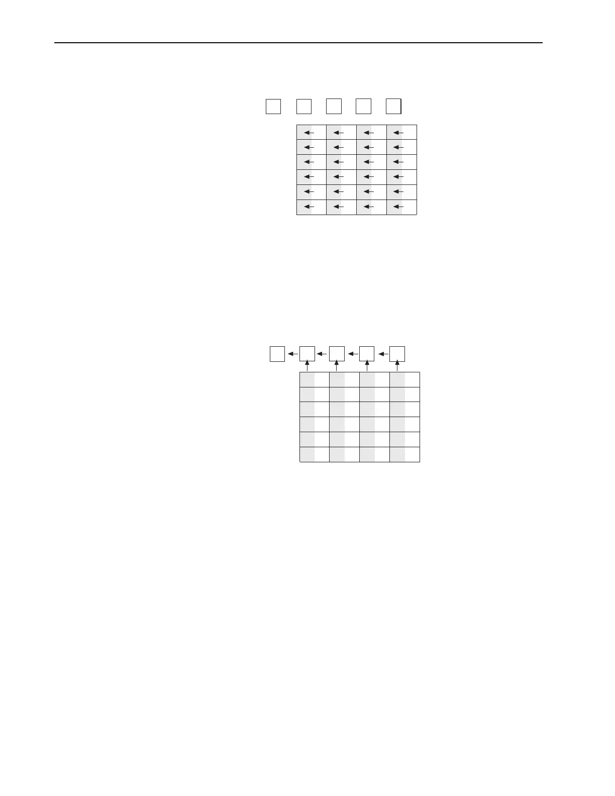
Figure 5-7 shows the situation early in the readout cycle. The charge in the
imaging areas has been transferred to the adjacent masked areas and up-shifting
to the readout register has started. Note that a second exposure does not begin
while the readout is in progress because the intensifier is not gated on at this
time.
Figure 5-7: Step 2: Non-Overlapped, Early Readout
3.
Figure 5-8 shows the transfer to the output node. The lowermost pixel in each
column is shown empty. Each row of charges is moved in turn into the readout
register, and from there to the output node and off of the array for further
processing. The process continues until all charges have been completely
transferred out of the array. The image intensifier is off during this time so no
signal charge is accumulated, but dark current does accumulate. Because this
scheme is less time efficient than that used in the overlapped mode, the frame
rate may be lower in non-overlapped operation than it is in overlapped
operation with the some gating setups.
1
Empty Readout Register. Exposure
has ended and image is being
transferred to masked areas..
A2
A1
B2
B1
A4
A3
B4
B3
A6
A5
B6
B5
C2
C1
C4
C3
C6
C5
D2
D1
C4
D3
D6
D5
A1 B1
C1
A2 B2
A4
A3
B4
B3
A6
A5
B6
B5
C2
C4
C3
C6
C5
D2
D4
D3
D6
D5
D1
Image has been shifted to masked areas and
first line has been shifted to Readout Register.
2