Chapter 9 LightField and Dual Image Feature 165
Because the Shift Behind Mask operation occurs during the acquisition of the first frame
of image intensity data, not all Frame 1 data are shifted. Consequently, the unshifted data
are then added to the subsequent Frame 2 image data, resulting in:
• An incomplete/erroneous set of Frame 1 data;
• Corrupt Frame 2 data.
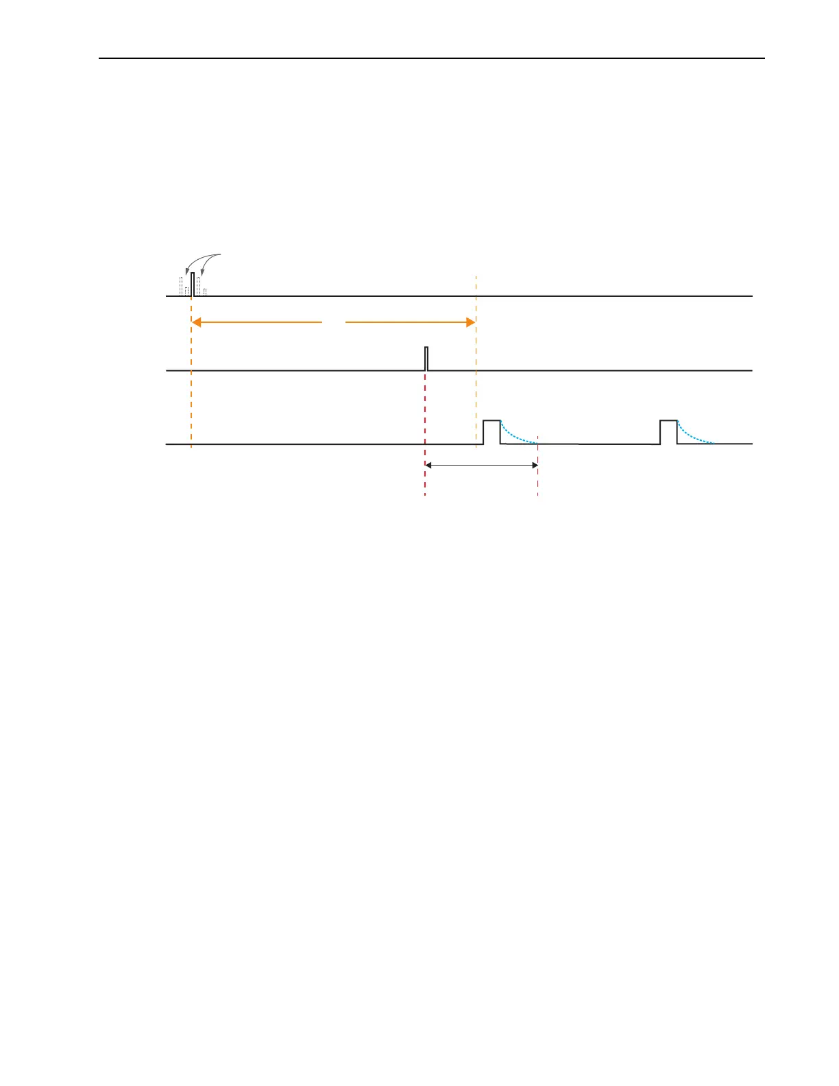
Figure 9-12 illustrates the timing diagram for the worst-case scenario where the
Shift
Behind Mask
operation is completed prior to the first frame of image data’s being acquired.
Figure 9-12: Timing Diagram: Pre-Trigger With Very Late Input Trigger
In this case, data from the first frame is added to data from the second frame, resulting in:
• One “non-existent” frame, and
• One corrupt frame comprising two frames’ worth of data.
IMAGES
TRIGGER
t
FF
FIRST FRAME
SECOND FRAME
t
PT
: Time between Pre-Trigger and
Shift Behind Mask PS ± 2 PS)
t
FF
: Time to Acquire First Frame of Image Data
PRE-TRIGGER
t
PT
Shift Behind
Mask
Pre-Trigger
Jitter