Chapter 6 LightField and Gated Operation 115
c. The SyncMASTER ON button enables the SyncMASTER trigger output from the
SyncMASTER1 and SyncMASTER2 connectors on the
AUX I/O cable. The
frequency for the SyncMASTER outputs may then be configured, as well as the
AUX Output signal at the AUX OUT connector on the rear of the PI-MAX4.
• When SyncMASTER is enabled, the output of the SyncMASTER1
connector will be at the frequency specified on the Internal Trigger
Frequency field.
• The output of the SyncMASTER2 connector will be at the same frequency
as that of
SyncMASTER1. However, a delay can be specified so the edges
of
SyncMASTER2 will occur after the edges of SyncMASTER1.
• When using the AUX Output signal from the SuperSYNCHRO to trigger a
piece of equipment, enter the Auxiliary pulse delay time. Enter the pulse
width needed to trigger the equipment.
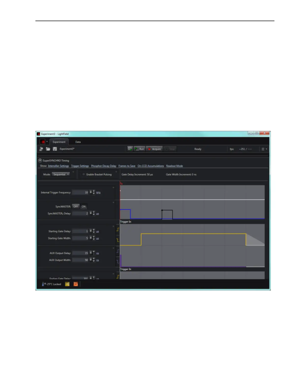
Figure 6-16 illustrates SuperSYNCHRO Timing with SyncMASTER on.
Figure 6-16: Typical SuperSYNCHRO Timing: SyncMASTER On