Chapter 7 WinX and Gated Operation 147
7.5.1.2 SyncMASTER1 Supplies the Master Clock
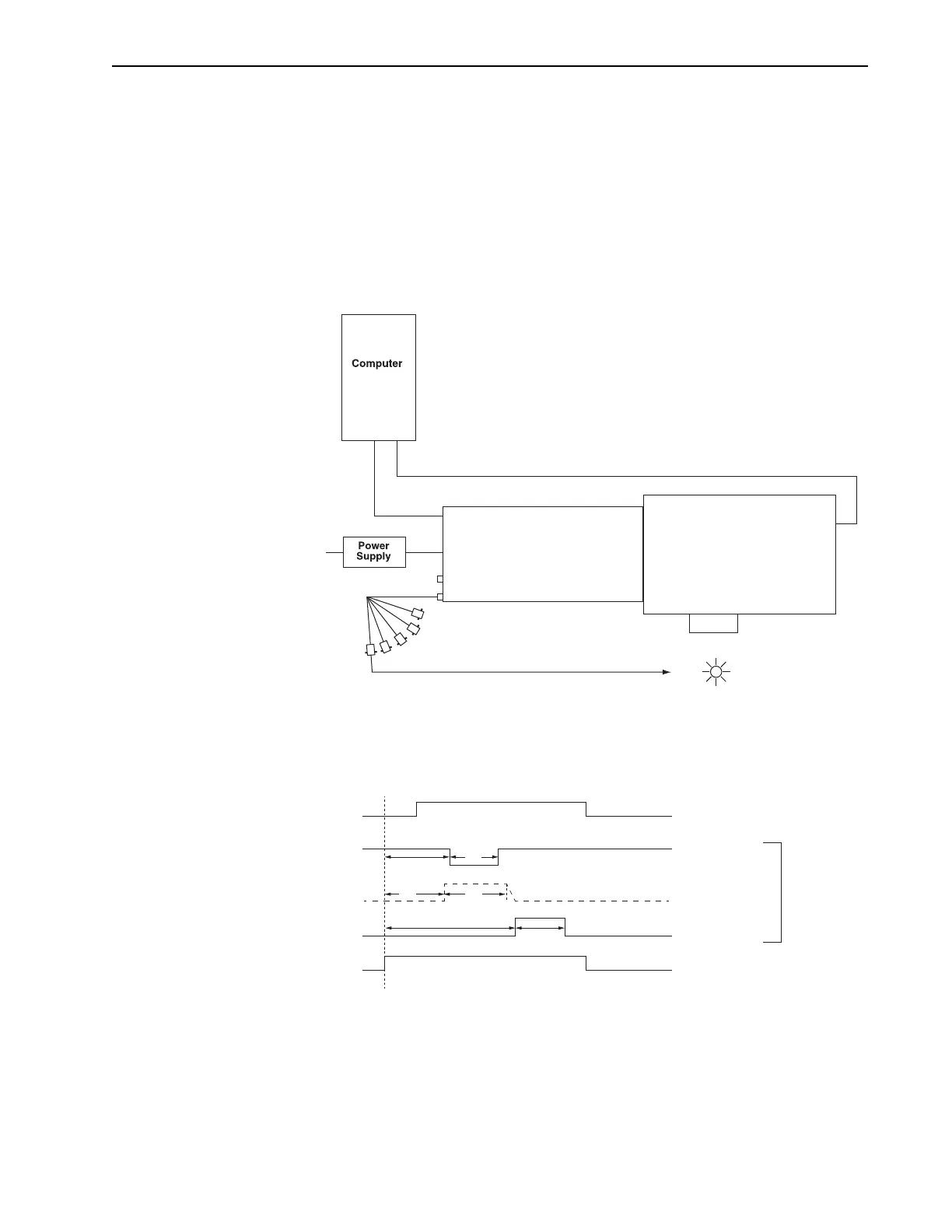
When using a light source that has a
Trigger In, the PI-MAX4 SyncMASTER function can
be used as the Master clock. The setup procedure is similar that described in Section 7.5.1.1,
Experiment Supplies the Master Clock, with the following changes:
• Internal Trigger is selected;
•SyncMASTER is enabled;
• A cable is required between the PI-MAX4 AUX I/O cable SyncMASTER1 BNC
and the light source (i.e., experiment,) for triggering the event. See Figure 7-23
Figure 7-23: Block Diagram: SyncMASTER1 as Master Clock
Figure 7-24 illustrates the timing diagram for this experiment configuration.
Figure 7-24: Timing Diagram: SyncMASTER1 as Master Clock
PI-MAX4 Spectrograph
AUX I/O
AUX OUT
96-264
GigE
USB
AUX I/O Cable
SynchMASTER1 Out
SyncMASTER1 OutSyncMASTER1 Out
AUX OUT
MCP Gating
Off
Off Off
T0 (on AUX I/O cable) T0 (on AUX I/O cable)
MCP Gating
Photocathode GatingPhotocathode Gating
Off
On
On
AUX OUT
T0 (on AUX I/O cable)
Delay and Width
are User-Settable
Based on Internal
Trigger Frequency