270 PI-MAX
®
4 System Manual Issue 9
A.6 AUX I/O Interface
The AUX I/O interface provides access to the trigger function, DAC, and TTL signals via a
rear panel connector and an AUX I/O cable that is supplied with each PI-MAX4 system.
This section provides pinout information for both the rear panel AUX I/O connector as well
as the AUX I/O Cable.
Table A-5 provides TTL signal-specifications for the AUX I/O interface.
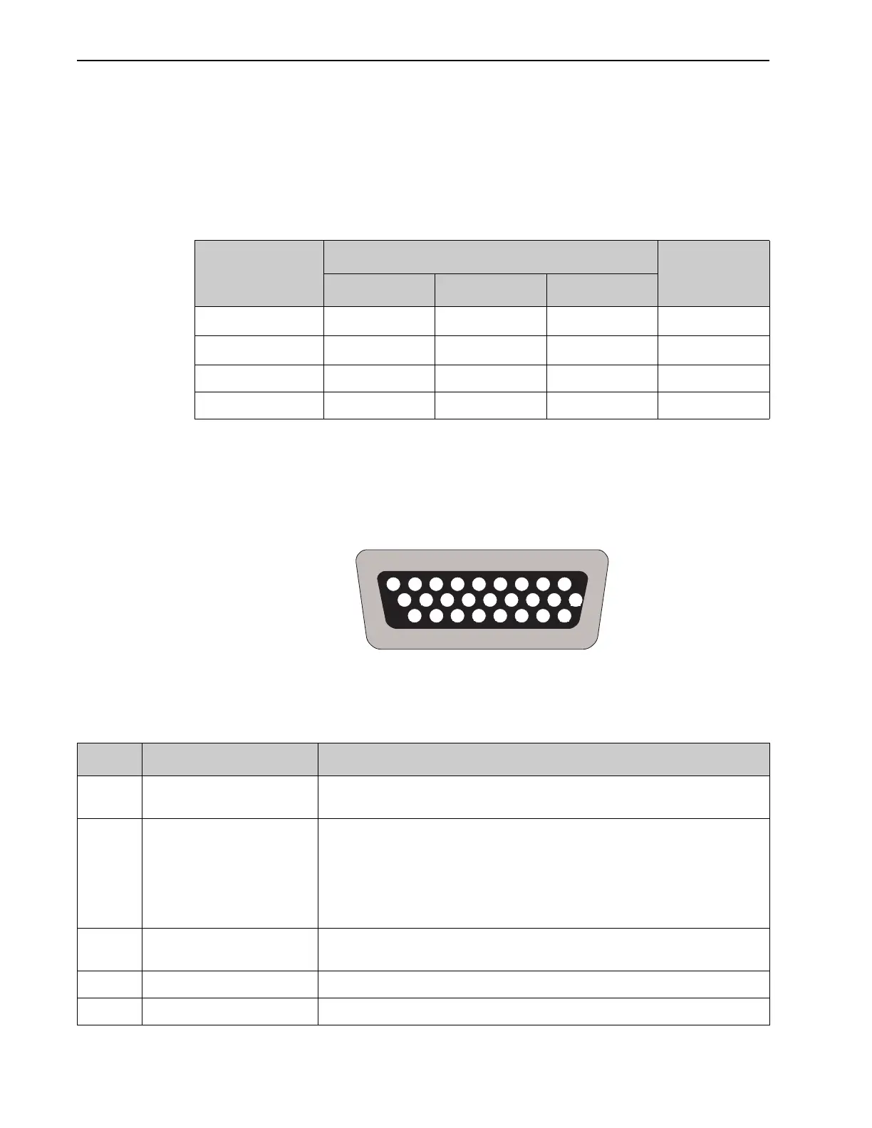
The AUX I/O connector is located on the rear of the PI-MAX4 chassis. It is a female, DB26,
high-density connector.
Figure A-1 illustrates the pinout of the AUX I/O connector, viewed from the rear panel of
the PI-MAX4 chassis, with each contact/pin identified by its pin number.
Figure A-1: AUX I/O Connector Pinout
Table A-6 provides complete information about each AUX I/O pin and signal sorted by pin
number.
Table A-5: AUX I/O Interface TTL Signal Specifications
Parameter
Specification
Unit
Minimum Nominal Maximum
V
IN
(logic 1) 2.4 — — V
DC
V
IN
(logic 0) — — 0.9 V
DC
Rise Time 40 ns
Duration 100 ns
10
2526 24 23 22 21 20
19
89 7 6 5 4 3 2
1
1718 16 15 14 13 12 11
Table A-6: AUX I/O Connector Pinout and Signal Descriptions (Sheet 1 of 2)
Pin # Signal Name Description
1 T0 Output LVCMOS FPGA output with limited ESD protection, goes high at T0. Indicates a
trigger has been received.
2 Pre-Trigger Input LVCMOS ESD-protected input. Pre-Trigger is an optional signal that may be used to
terminate the continuous cleans instruction operation. In ordinary operation there is a
one clean cycle jitter between the trigger and the finish of cleaning (i.e., the clean
cycle in process must be completed.) A rising edge will cause a pre-trigger.
NOTE: The camera must already be in Acquire mode before the pre-trigger is sent
to the input.
3 GND System chassis ground. Any external circuitry intended to interface with the trigger
control signals must reference this ground connection.
4 Lockout Output LOW indicates I.I.T. is locked off.
5 — Not Used