Home
Quantum
Storage
Scalar i6000
Installation Guide
Page 127 (Figure 12 Example of Drives Connected to FC I;O Blades)
Quantum Scalar i6000 - Figure 12 Example of Drives Connected to FC I;O Blades
384 pages
Manual
To Next Page
To Next Page
To Previous Page
To Previous Page
Loading...
Scalar i6000 Installation Guide
115
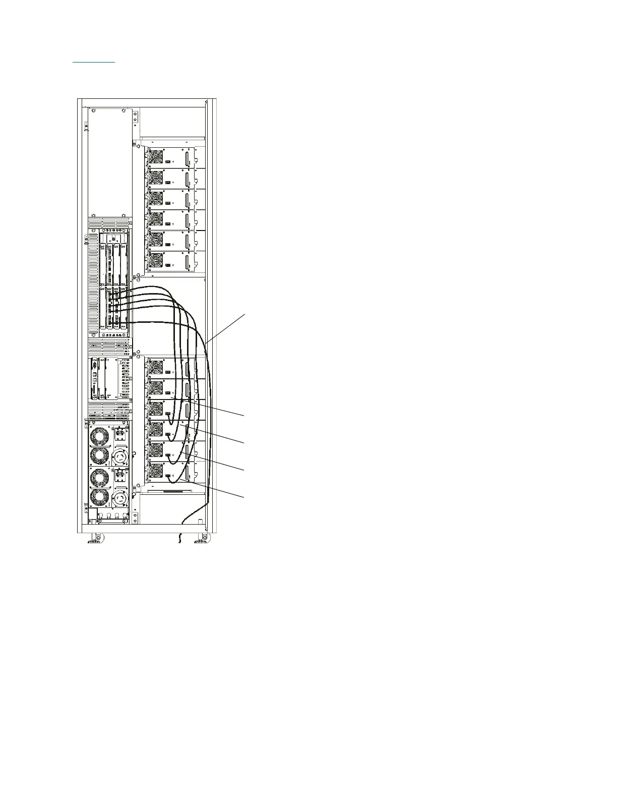
Figure 12
shows an example of drives connected to the FC I/O blades.
Figure 12
Example of Drives Con
nected to FC I/O Blades
Drives can only be co
nnected to ports FC-3 thr
ough
FC-6. Host connectio
ns are made through po
rts FC-1
and FC-2.
connection to host or SAN
cable from
FC-3 to drive
coordinate
1,1,1,1,1,1
cable from
FC-4 to drive
coordinate
1,1,1,2,1,1
cable from
FC-5 to drive
coordinate
1,1,1,3,1,1
cable from
FC-6 to drive
coordinate
1,1,1,4,1,1
126
128
Table of Contents
Main Page
Default Chapter
3
Table of Contents
3
1 About this Guide and Your Product
13
Product Safety Statements
13
Mechanical Locks
14
Door Interlock Switches
14
Power Button on the Library's Indicator Panel
14
Physically Accessing the Library
14
Performing Mechanical Maintenance
15
General Guidelines
15
Working on Live Components
16
Mercury Statement
16
Disposal of Electrical and Electronic Equipment
17
Product Model Number
18
Explanation of Symbols and Notes
18
Other Documents You Might Need
18
Getting more Information or Help
19
2 Getting Started
21
Unpacking and Inspecting
21
Checking the Accessories
22
Initial Setup Procedure Road Map
23
Required Tools
25
Table 1 Required Tools for Installing a Library
25
Illustrations of Modules
26
Figure 1 Front View of an 8-Module Library
26
Figure 2 Front View of a Two-Module Library
27
Figure 3 Control Module, Front View Component Location
28
Figure 4 Control Module, Rear View Component Location
29
Figure 5 Expansion Module, Back View Component Location
30
3 Installing a Stand-Alone Control Module
31
Positioning the Stand-Alone Control Module
32
Lowering the Leveling Legs
32
Raising the Control Module off the Casters
33
Testing the Digital Level
34
Verifying Level Condition
35
Additional Leveling
36
Setting the Leg Lock Nuts
37
4 Installing a Multi-Module Library
39
Preparing to Install a New Multi-Module Library
40
Attaching Control and Expansion Modules as System Units
40
Aligning and Bolting the Frames
40
Lowering the System Unit Leveling Legs
42
Positioning the System Unit
42
Raising the System Unit off the Casters
43
Testing the Digital Level
43
Verifying Level Condition
45
Additional Leveling
46
Lowering All Other Leveling Legs
47
Setting the Leg Lock Nuts
47
Adding an Expansion Module to an Existing System Unit
48
Installing Expansion Modules after Installing the System Unit
49
Lowering the Leveling Legs
49
Positioning the New Expansion Module
49
Raising the Expansion Module off the Casters
50
Aligning the New Expansion Module with the System Unit
51
Inserting the Attachment Bolts
51
Tightening the Attachment Bolts
52
Setting the Leg Lock Nuts
52
Attaching the X-Axis Rails
53
Attaching and Aligning the Upper and Lower X-Axis Rails
53
Attaching the Middle X-Axis Rail
55
Aligning the Middle X-Axis Channel
57
Aligning the Middle X-Axis Rail
58
Verifying the Middle X-Axis Rail Alignment
59
Verifying Accessor Assembly Alignment
61
Attaching the Tensioner Bracket and Hard Stop
62
Eight Modules or Less Configuration
62
Nine Modules or more Configuration
63
Installing the X-Axis Belt
65
Installing the X-Axis Chain Assembly
70
Installing the X-Axis Chain Trough
75
Routing and Connecting Module Cables
77
Assembling the Last Expansion Module
82
Preparing an Existing Library to Receive an Expansion Module
86
Positioning the Existing Library
86
Removing the Right Side Panel from the Last Existing Module
87
Removing the X-Axis Belt
91
Removing the Tensioner Bracket and Hard Stop
92
Removing the Middle X-Axis Rail from Module Eight
93
Removing the X-Axis Chain Assembly
94
Removing the LBX Terminator Board
97
Removing and Replacing the LBX Board
98
Removing the LBX Board
98
Replacing the LBX Board
100
Removing and Replacing the IEX Card
101
Removing the IEX Board
101
Replacing the IEX Board
102
5 Applying Power
105
Supported AC Power Cables
105
Table 2 Electrical Specifications for Control and Expansion Modules
105
Powering on the Library
106
Figure 6 Library Management Console Touch Screen
108
6 Installing Drives and Blades
109
Referencing Tape Drive Compatibility
110
LTO Drives
111
Table 3 LTO Drive and Cartridge Compatibility
111
Table 4 DLT Drive and Cartridge Compatibility
112
Figure 7 Drive Numbering Sequence in the Control Module and Expansion Modules
113
FC I/O Blade Numbering Sequence
114
Figure 8 Fibre Channel I/O Blade Connection Numbering Sequence
114
Ethernet Expansion Blade Numbering Sequence
115
Numbering Sequences
113
Drive Numbering Sequence
113
DLT Drives
112
Figure 9 Ethernet Expansion Blade Connection Numbering Sequence
115
Figure 10 I/O Management Unit Bay Layout
116
Figure 11 LTO Drive Examples
118
Installing Blades in the I/O Management Unit
120
I/O Management Unit Bay Numbering Sequence
116
Installing Drives
117
7 Cabling
123
Drive Cabling Considerations and How Drive Connection Model Affects Library Control Paths
124
Cabling Configuration for Storage Networking Drives
124
LTO-5 SNW Drives
124
Pre LTO-5 SNW Drives
124
Cabling Configuration for Native Attach Drives
124
Pre LTO-5 Native Attach Drives
124
LTO-5 Native Attach Drives
125
Interaction of Physical Cabling and Library Configuration Options
125
Attaching Drives to FC I/O Blades
125
Table 5 Cable Connection Requirements for FC Drives
126
Table 6 Cable Connection Recommendations for Ethernet Expansion Blades
131
Figure 14 Example of Direct Attached Library with SCSI Drives
138
Figure 15 Example of Direct Attached Library with FC Drives
139
Connecting FC Drives to Hosts
140
Connecting SCSI Drives to Hosts
141
Figure 13 Example of LTO-5 Drives Connected to Ethernet Expansion Blades
132
Connecting LTO-5 Drives to Ethernet Expansion Blades
133
Attaching FC and SCSI Drives Directly to Hosts
136
Attaching Hosts to FC Ports
136
Figure 12 Example of Drives Connected to FC I/O Blades
127
Connecting FC Drives to FC I/O Blades
128
Attaching FC LTO-5 Drives to Ethernet Expansion Blades
131
8 Installing Cartridges
143
Loading Cartridges
143
Figure 16 Aisle, Module, and Rack Numbering Locations
144
Storage Addressing System Overview
144
Figure 17 Section, Column, and Row Numbering Locations for Rack 1 Using LTO Cartridges
145
Figure 18 Section, Column, and Row Numbering Location for Rack 2 Using LTO Cartridges
146
Figure 19 Example Location Coordinates
147
Figure 20 Location Coordinates Used in the Load Drives Dialog Box
148
Figure 21 Applying Barcode Labels to LTO Cartridges
149
Barcode Requirements
150
Importing Cartridges Using the I/E Station
151
Manually Bulk Loading Cartridges
154
Installing Barcode Labels
149
Figure 22 Cartridge Insertion into Magazine
154
9 Setting up Your Library for Access
157
Launching the Remote Client
157
Configuring Library Security
158
Changing Internal IP Network Addressing
158
Changing the Library Security Configuration
160
Accessing the Security Configuration
160
Configuring Access for Network Services
160
Configuring Access for Remote LMC Clients
161
Configuring Access for SNMP and SMI-S
163
10 Configuring the Library
165
Addressing Configuration Prerequisites
165
Logging on to the Library
166
Performing Basic Configuration
168
Deleting the Default Partition
169
Running the Setup Wizard
170
Performing Advanced Configuration
175
Enabling Licenses
176
Setting up the Network Configuration
177
Setting up Ipv4 Network Configuration
178
Setting up Ipv6 Network Configuration
179
Setting Date and Time
181
Setting up E-Mail
182
Setting up Notification
183
Enabling Logical Serial Number Addressing for Drives
187
Using LDAP
188
LDAP Server Guidelines
188
Openldap 2.4
188
User and Group Access
188
Configuring LDAP
189
Working with Library Control Paths
192
Table 7 Control Path Matrix
193
Table 8 Return Media Identifier Behavior Example
199
Table 9 FC I/O Blade Default Port Settings
206
Configuring FC Host Port Failover
210
Enabling a Disabled Target Port
212
Configuring Datapath Conditioning
213
Configuring FC Host LUN Mapping
216
Configuring Host Access
216
Configuring Switch Zoning
216
FC Host LUN Mapping
216
Channel Zoning
220
Configuring FC Channel Zoning
220
SCSI Host LUN Mapping
221
LUN Mapping Wizard
223
Configuring Control Path
227
Setting up Control Path and Storage Networking
227
Selecting a Storage Networking Drive
229
Configuring the SNW Host Device
230
Putting a Partition Online
232
Putting Physical Library and Partitions Online
232
Putting the Physical Library Online
232
Online and Offline Functionality
234
Table 10 Library Functions Requiring Online or Offline State
234
Assigning Cleaning Magazines and Importing Cleaning Media
235
Configuring Drive Cleaning
235
Exporting Cleaning Media
237
Unassigning a Cleaning Magazine
237
Configuring Screen Saver Preferences
238
Saving the Library Configuration
240
Logging off
241
Performing Simple Partition Resource Allocation
200
Performing Expert Partition Resource Allocation
202
Viewing Partition Details
204
Configuring FC I/O Blade Ports
206
Creating Partitions
194
Creating Partitions Automatically
194
Creating Partitions Manually
196
11 Adding Optional Hardware
243
Shutting down the Library
244
Adding Drives to an Existing Installation
245
Drive Numbering Sequence
246
Figure 23 Drive Sled Positions
246
Figure 24 I/O Management Unit Bay Layout
265
Adding Blades to the I/O Management Unit
269
Installing the I/O Management Unit Cooling Assembly
269
Installing a Control Management Blade
271
Installing an FC I/O Blade
272
Installing an Ethernet Expansion Blade
276
Adding a 24-Slot I/E Station to an Expansion Module
281
Adding a 72-Slot I/E Station to an Expansion Module
293
Adding Aisle Lights
309
Adding a Power Supply Chassis
252
Adding a Redundant Power Supply
256
Adding an I/O Management Unit
259
12 Installation Testing and Verification
319
Verifying the Hardware Installation
319
Installation Verification Test Overview
321
Figure 25 Verification Tests Dialog Box
322
Installation Verification Test Functions
322
Library Alignment Test
322
Table 11 Test Results
325
Figure 26 Report Window
326
Figure 27 Joint Alignments Graphical Report
327
Joint Alignments
327
Figure 28 Vertical Alignments Graphical Report
328
Vertical Alignments
328
Figure 29 Horizontal Alignments Graphical Report
329
Horizontal Alignments
329
Calibration Offsets
330
Figure 30 Calibration Offsets Graphical Report
330
Boundary/Accessibility
331
Figure 31 Boundary/Accessibility Graphical Report
331
Figure 32 Get/Put Graphical Report
332
Get/Put
332
Figure 33 Scan Fiducials Graphical Report
333
Scan Fiducials
333
Figure 34 Picker Pivot/Reach Graphical Report
334
Picker Pivot/Reach
334
Verification Test Logs
335
Test Results
325
Verification Test Graphical Reports
326
Get/Put Test
323
I/E Station Assembly Test
323
Library Inventory
323
Picker Assembly Test
323
Scanner Fiducial Test
323
Blade Inventory
324
Drive Inventory
324
Figure 35 Example Test Log Output
336
Figure 36 Comparison of LBX Board Versions
358
Figure 37 LBX Connections (LBX2 Gen 2)
359
Figure 38 LBX Connections (LBX2 Gen 3)
360
Figure 39 Comparison of LBX Terminator Versions
361
Figure 40 LBX Board and Terminator Installed
361
Figure 41 Locations and Colors of Blade Status Leds
364
Table 16 Explanations of Blade Status LED States
364
Actions Based on LED States
365
Table 17 Explanations of Blade Status LED States under Normal Conditions
365
Figure 42 Rear View of Fibre Channel Drive Sled (UDS-2)
366
Interpreting Drive Status Leds
366
Figure 43 Rear View of Fibre Channel Drive Sled (UDS-3 LTO-4 and LTO-5 Drives))
367
Table 18 Explanations of Drive Sled Status LED States (UDS-2 and UDS-3)
367
Drive Sled Fibre Channel Link LED
368
Interpreting Fibre Port Link Leds
368
Table 19 Explanations of Drive Sled Status LED States under Normal Conditions
368
Table 20 Explanations of Ethernet Port LED States
368
FC I/O Blade Fibre Port Link LED
369
Table 21 Explanations of Fibre Drive Sled Link LED States (UDS-2)
369
Table 22 Explanations of Fibre Drive Sled Link LED States (UDS-3)
369
Figure 44 Locations and Colors of I/O Blade Fibre Port Link Leds
370
Table 23 Explanations of I/O Blade Link LED States
370
Ethernet Expansion Blade Leds
371
Figure 45Location and Colors of Ethernet Expansion Blade Status Leds
371
Table 24 Explanations of Ethernet Expansion Blade LED States
371
Table 25 Explanations of EEB Ethernet Port LED States
371
Figure 46 Locations and Colors of MCB Ethernet Port Leds
372
Interpreting MCB Port Leds
372
MCB Ethernet Port Leds
372
Table 26 Explanations of MCB Ethernet Port LED States
372
Figure 47 Locations and Colors of MCB Fibre Channel and SCSI Port Leds
373
MCB Fibre Channel and SCSI Port Leds
373
Figure 48 Locations of LBX Terminator Leds (Version 01)
374
Interpreting LBX Terminator Leds
374
LBX Terminator Version 01 Leds
374
Table 27 Explanations of LBX Terminator LED States (Version 01)
374
Figure 49 Locations of LBX Terminator Leds (Version 03)
375
LBX Terminator Version 03 Leds
375
Table 28 Explanations of LBX Terminator LED States (Version 03)
375
Figure 50 Locations and Colors of Power Supply Leds
376
Interpreting Power Supply Leds
376
Table 29 Explanations of Power Supply LED States
376
D Glossary
377
LBX Terminator
361
C Interpreting LED Codes
363
Interpreting Blade Status Leds
363
Running the Installation Verification Test
337
Completing the Installation Verification Checklist
344
Table 12 Automatic E-Mail Notification
345
Table 14 Library Partitioning
346
Table 13 Customer License Verification
346
Table 15 FC I/O Blade Default Port Settings
347
A Testing and Calibrating the Digital Level
349
Testing the Digital Level
349
Calibrating the Digital Level
351
B LBX Board and Terminator
357
LBX Board
357
Other manuals for Quantum Scalar i6000
User Guide
738 pages
Planning Guide
92 pages
Manual
58 pages
Replacement
12 pages
Quick Start Guide
24 pages
Related product manuals
Quantum Scalar i6
44 pages
Quantum Scalar i3
44 pages
Quantum Scalar i40
404 pages
Quantum Scalar i80
404 pages
Quantum Scalar i500
575 pages
Quantum Scalar i2000
447 pages
Quantum Scalar 1000
284 pages
Quantum LTO-8 HH SAS
126 pages
Quantum LTO-9 HH SAS
120 pages
Quantum Superloader 3
306 pages
Quantum StorNext M660
2 pages
Quantum QXS-424
58 pages

 Loading...


