24 Installing a Stand-Alone Control Module
Additional Leveling
Customer floors may be such that further leveling is required. The goal in leveling the control module is to
adjust the leveling legs to achieve a digital level reading that is 0.00 +/- 0.30.
1 Place the digital level inside the access door. Use the following rules when leveling from left to right:
• Rule 1: Always make your leveling adjustments to raise the control module (turn the legs clockwise
looking from the top).
• Rule 2: Since the control module frame is very stiff, adjust the appropriate left or right leg pair the
same amount when leveling left to right.
• Rule 3: Use small adjustment increments; no more than one half (½) turn at a time.
• Rule 4: If the leveling adjustment has raised any of the other leveling legs off the floor, take out the
adjustment and work on the opposite end of the control module (front to back).
• Rule 5: Wait at least 10 seconds for the digital level to settle between adjustments.
2 Place the level on the left side inside the access door. Use the following rules when leveling from front
to back:
• Rule 1: Always make your leveling adjustments to raise the control module (turn the legs clockwise
looking from the top).
• Rule 2: Since the control module frame is very stiff, adjust the appropriate front or rear leg pair the
same amount when leveling front to back.
• Rule 3: Use small adjustment increments; no more than one half (½) turn at a time.
• Rule 4: If the leveling adjustment has raised any of the other leveling legs, take out the adjustment
and work on the other side.
• Rule 5: Wait at least 10 seconds for the digital level to settle between adjustments.
Make sure the digital level is not resting on any frame welds or debris that
would cause an inaccurate reading. To find the small circular frame welds,
run your finger tips over the spot where you are going to place the level.
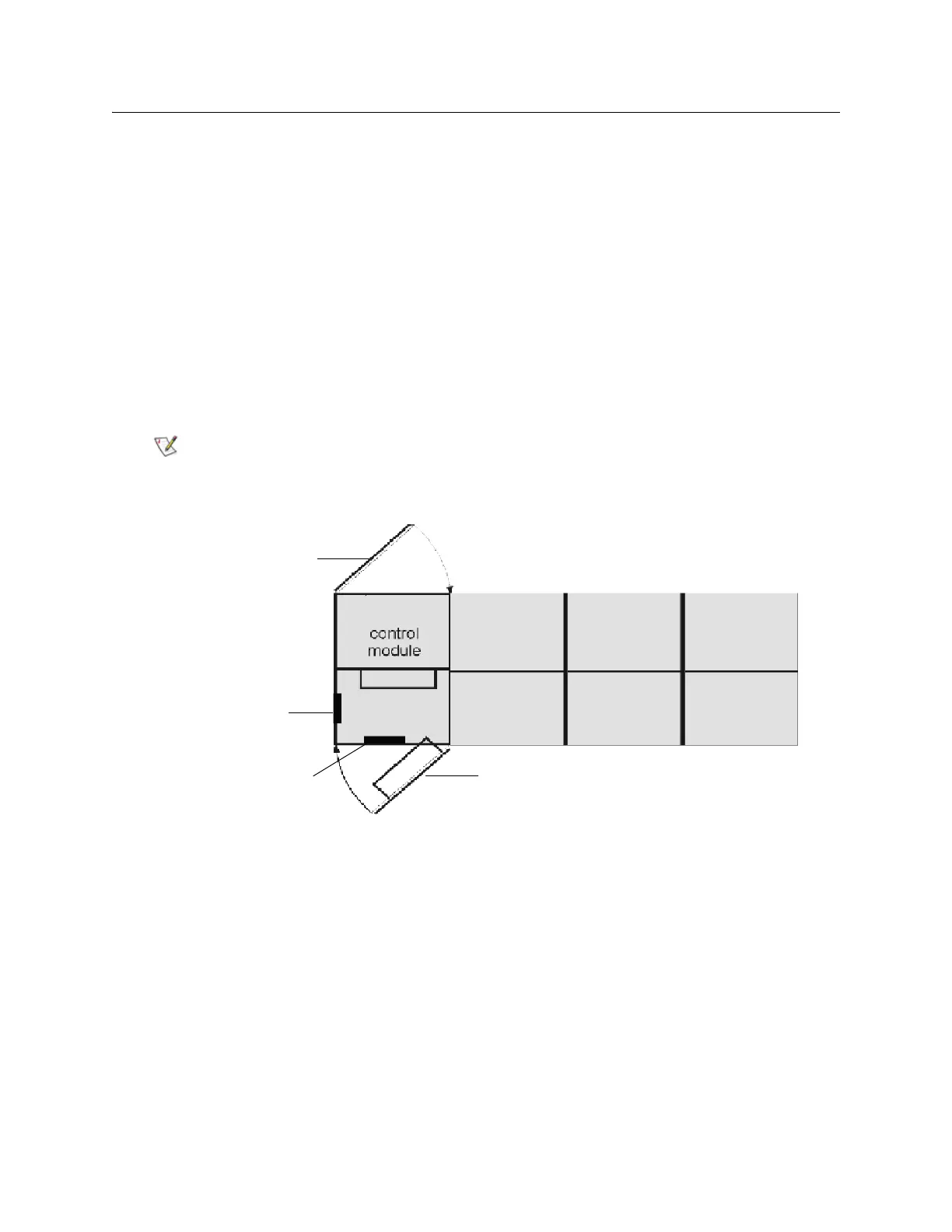
access door
digital level position #1
service door
digital level position #2
front to back
left to right

 Loading...


