260 Adding Optional Hardware
7 Use your thumbs on each end of the blade to evenly apply pressure and slide it into the I/O management
unit. When you feel the pins of the CMB lock into the backplane, push the latchhooks towards the middle
of the blade and into the lock position.
8 Detach the ESD strap and close the door.
Installing an FC I/O Blade
Required tools: ESD strap
1 Open the service door of the module.
2 Attach the ESD strap to your wrist and to an unpainted surface inside the door.
3 Remove the cover plate from bay where the FC I/O blade will be installed. The population order for the
FC I/O blades is shown below.
4 Remove the FC I/O blade from the protective anti-static bag.
5 Press up and out to open the latchhooks on each side of the FC I/O blade.
Slots that are not populated with blades must contain a cover plate. If
the cover plates are not installed, FC I/O blade temperature errors will
occur.
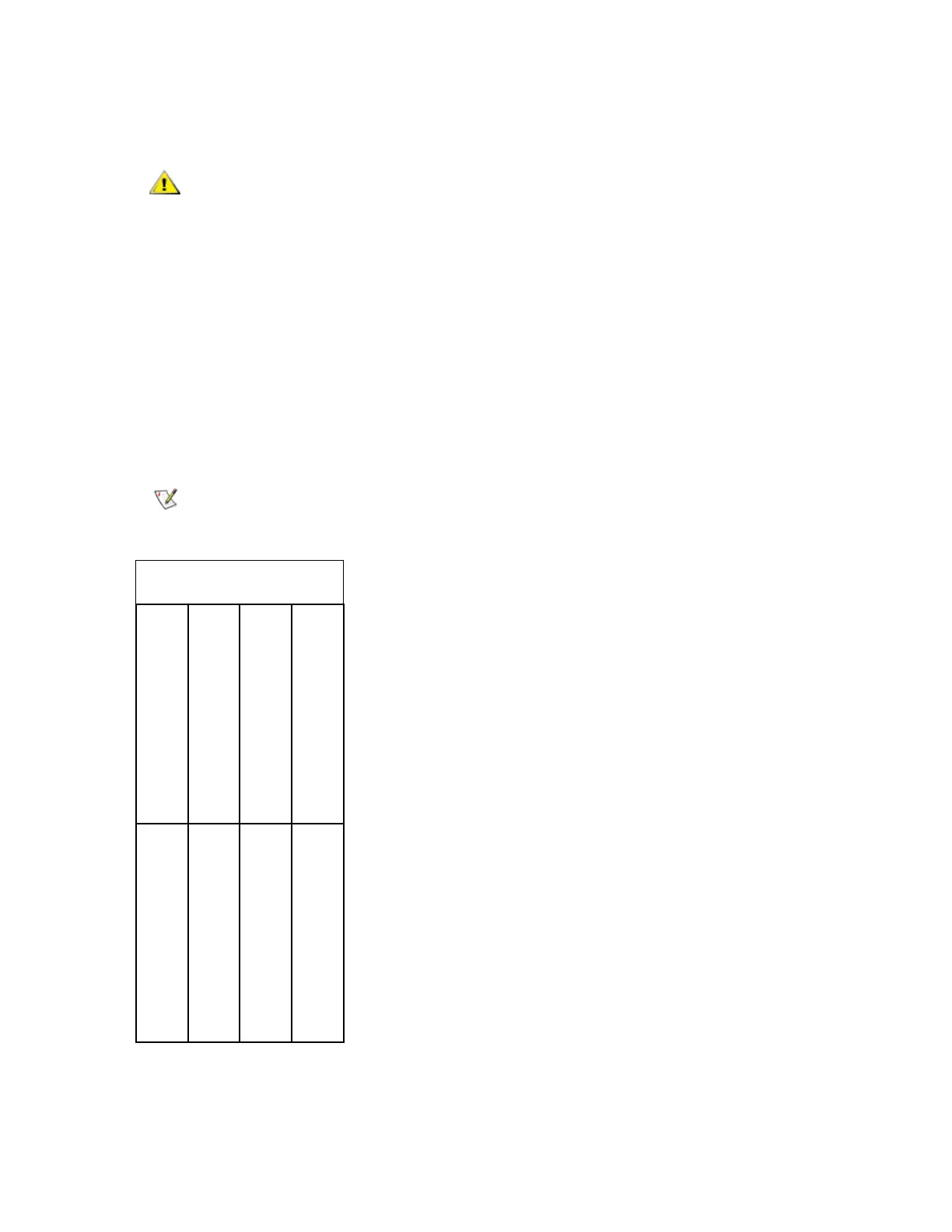
Make sure you install the FC I/O blade into the correct bay.
bay 1 (not used)
bay 3 (first FC I/O blade)
bay 5 (third FC I/O blade)
bay 4 (second FC I/O blade)
bay 6 (not used)
bay 8 (second Ethernet
cooling assembly
bay 7 (first Ethernet
bay 2 (CMB)
expansion blade) expansion blade)

 Loading...


