Scalar i6000 Installation Guide 355
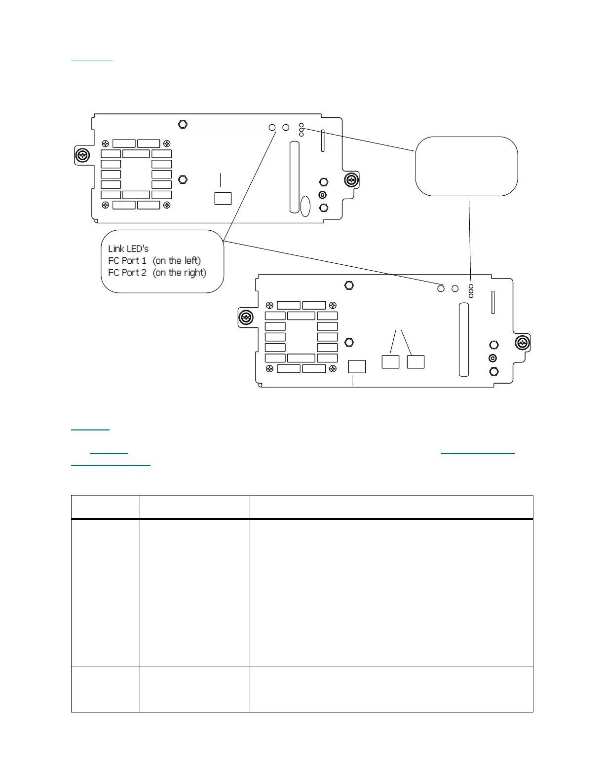
Figure 43 shows the locations of the status LEDs and the Fibre Channel link LED on the rear of a UDS-3
drive sled.
Figure 43 Rear View of Fibre Channel Drive Sled (UDS-3 LTO-4 and LTO-5 Drives))
Table 18
describes how to interpret the drive sled status LED activity that you might see on the rear of a
UDS-2 or UDS-3 drive sled. For a description of how the blade status LEDs appear under normal conditions,
see Table 19
on page 356. For information about interpreting the drive link LED, see Drive Sled Fibre
Channel Link LED on page 356.
Table 18 Explanations of Drive Sled Status LED States (UDS-2 and UDS-3)
LED Color Represents Possible States and Explanations
Green Processor status • Solid on / solid off — tape drive’s main processor is not
operating
• Blinks one time every second (1 Hz) — drive sled’s main
processor is operating normally
• Two quick blinks within 1.25 seconds; then on solid for 1.25
seconds; repeat — tape drive sled firmware is downloading
• Three quick blinks within 1.25 seconds; then off for 1.25
seconds; repeat — tape drive is activating.
• Ten blinks in 1.25 second; then off for 1.25 seconds; repeat
— tape drive firmware is downloading
• Ten blinks per second — identify mode
Amber Health status • Solid off — drive sled’s controller (drive DC to DC converter
[DDC]) is operating normally
• Solid on — drive sled’s DDC has failed
- top = blue
- middle = amber
- bottom = green
status LEDs:
fibre ports
12
EEB port
fibre port
LTO-4
LTO-5

 Loading...


