352 Interpreting LED Codes
Figure 41 shows the locations and colors of the status LEDs of the five blades that can be in the library.
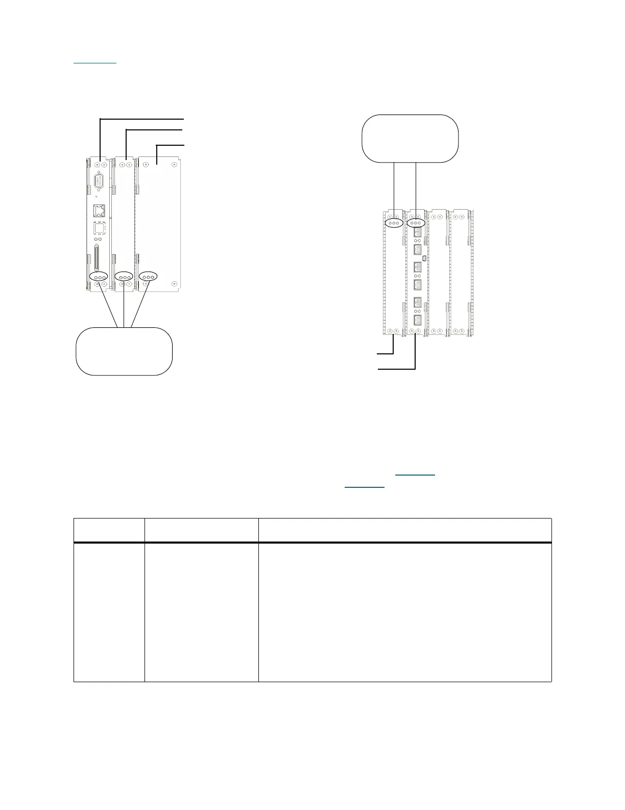
Figure 41 Locations and Colors of Blade Status LEDs
Blade status LEDs provide troubleshooting information that you can use in conjunction with tickets that the
library creates. However, the LEDs might not directly correspond to tickets. The LEDs can indicate a
firmware or hardware problem so severe that the library cannot create or display a ticket. For example, if
the MCB firmware becomes inoperable, the amber LED flashes at 1 Hz, but the library might not be able to
display any related tickets.
For a description of each LED color and what its state might mean, see Table 16
. For a description of how
the blade status LEDs appear under normal conditions, see Table 17
.
Table 16 Explanations of Blade Status LED States
LED Color Represents Possible States and Explanations
Green Processor status • Solid off — blade’s main processor is not operating (or blade
is booting)
• Solid on — blade’s main processor is not operating
(however, this does not apply to the LMD; solid on indicates
that the LMD’s main processor is operating normally)
• Blinks one time every second (1 Hz) — blade’s main
processor is operating normally
• Blinks 10 times every second (10 Hz) — identify mode
• Solid on for three seconds, then blinks twice at 1 Hz, and
then repeats — blade firmware is downloading
blade LEDs
- left = green
- middle = amber
- right = blue
blade LEDs
- left = blue
- middle = amber
- right = green
management control blade
robotics control unit
library motor drive
control management blade
FC I/O blade

 Loading...


