264 Adding Optional Hardware
Installing an Ethernet Expansion Blade
Required tools: ESD strap
1 Open the service door of the module.
2 Attach the ESD strap to your wrist and to an unpainted surface inside the door.
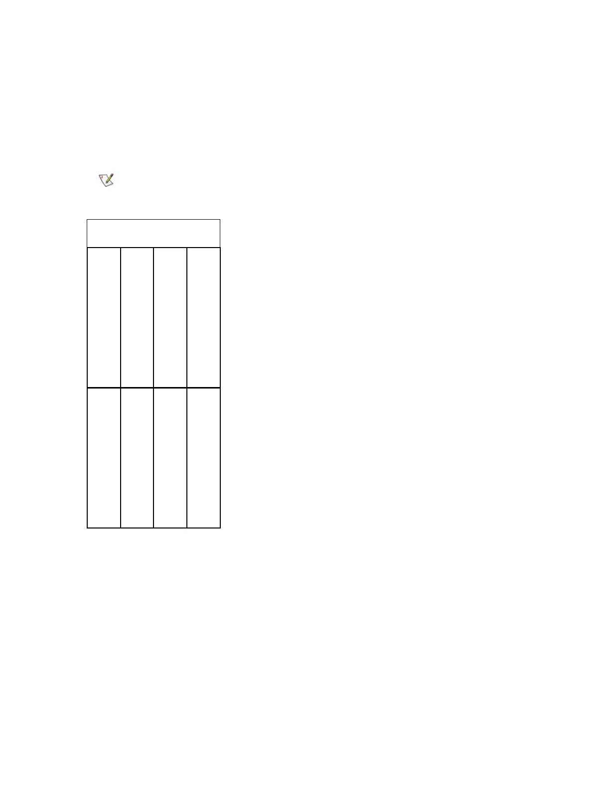
3 Remove the cover plate from bay where the Ethernet Expansion blade will be installed. The population
order for the Ethernet Expansion blades is shown below.
4 Remove the Ethernet Expansion blade from the protective anti-static bag.
5 Press up and out to open the latchhooks on each side of the Ethernet Expansion blade.
Make sure you install the EEB into the correct bay.
bay 1 (not used)
bay 3 (first FC I/O blade)
bay 5 (third FC I/O blade)
bay 4 (second FC I/O blade)
bay 6 (not used)
bay 8 (second Ethernet
cooling assembly
bay 7 (first Ethernet
bay 2 (CMB)
expansion blade) expansion blade)

 Loading...


