Scalar i2000 Installation Guide 265
6 Carefully align the blade with the guide slots in the bay. The status LEDs must be at the top.
7 Use your thumbs on each end of the blade to Figure 23
on page 234 evenly apply pressure and slide it
into the I/O management unit. When you feel the pins of the blade lock into the backplane, push the
latchhooks towards the middle of the blade and into the lock position.
8 Remove and discard the plastic covers from the Ethernet connector on the tape drives.
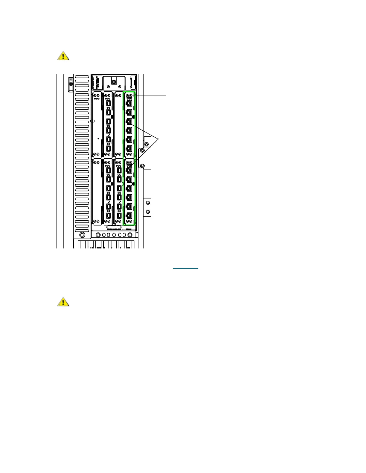
9 Remove and discard the protective covers from the ports on the Ethernet Expansion blades.
10 Carefully unwrap the EEB cables and remove the two plastic protective caps from each end of the cable.
Forcing the blade into the bay can cause the pins to bend.
Slots that are not populated with blades must contain a cover plate. If
the cover plates are not installed, blade temperature errors will occur.
Ethernet Expansion blades installed
status LEDs
in bays 7 and 8

 Loading...


