EasyManuals Logo

Quantum Scalar i6000 Installation Guide

Quantum Scalar i6000
384 pages
To Next Page IconTo Next Page
To Previous Page IconTo Previous Page
Page #260 background imageLoading...
Page #260 background image
248 Adding Optional Hardware
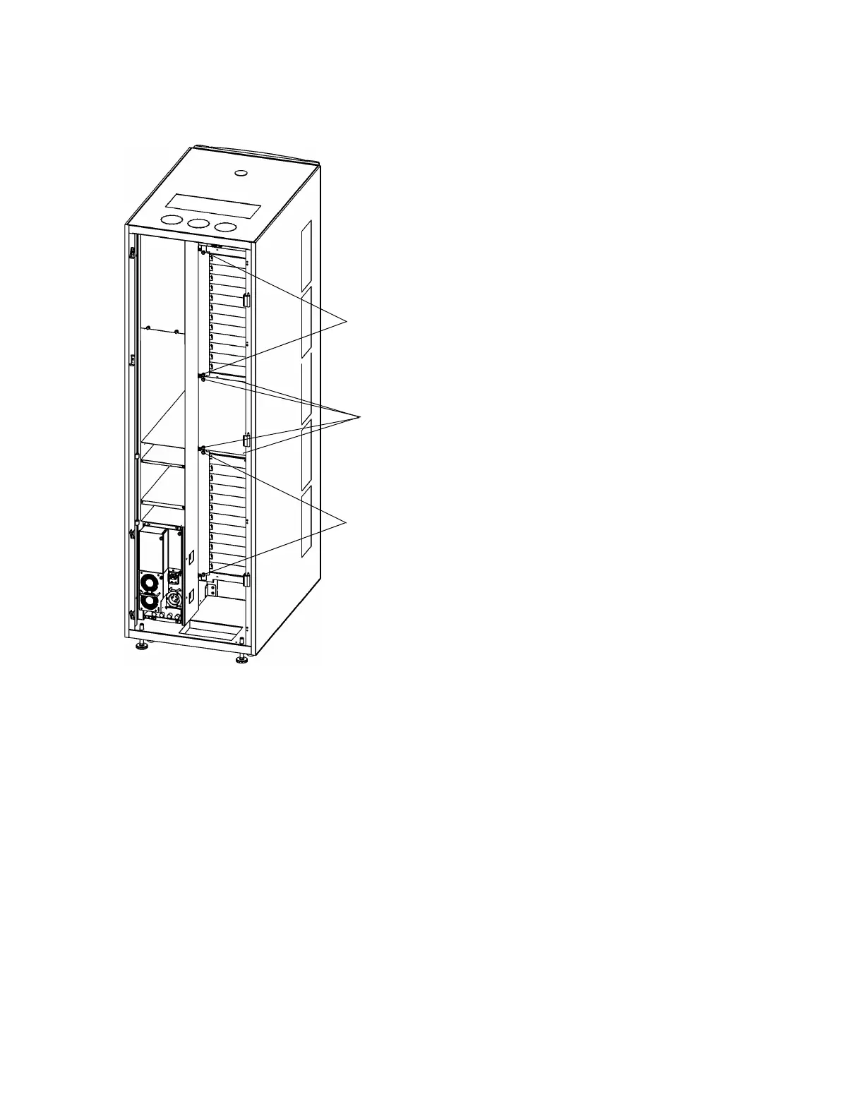
6 Use your fingers or a Phillips screwdriver to unscrew the two tall covers next to the drive clusters and
the mid-module cover plate. Remove the cover plates and set them aside. They will be reused later in
this procedure.
7 Open the box containing the new I/O management unit.
8 Feed the I/O management unit’s cables into the space behind where the I/O management unit is
installed. The cables must go downward towards the LBX board.
9 Insert the I/O management unit into the opening. Make sure the cables are not bent and continue going
down towards the LBX board.
thumbscrews
thumbscrews
thumbscrews

Table of Contents

Other manuals for Quantum Scalar i6000

Questions and Answers:

Question and Answer IconNeed help?

Do you have a question about the Quantum Scalar i6000 and is the answer not in the manual?

Quantum Scalar i6000 Specifications

General IconGeneral
Form FactorRack-mountable
InterfaceFibre Channel, SAS
Product TypeTape Library
CoolingRedundant cooling fans
DimensionsVaries by configuration
WeightVaries by configuration
Operating Humidity20% to 80% non-condensing
ScalabilityScalable
Drive TypesLTO
RedundancyRedundant power supplies
ManagementWeb-based management
Tape TechnologyLTO
Supported MediaLTO Ultrium 9, LTO Ultrium 8, LTO Ultrium 7, LTO Ultrium 6
Power SupplyRedundant power supplies
Non-operating Humidity5% to 95% non-condensing

Related product manuals