EasyManuals Logo

Quantum Scalar i6000 Installation Guide

Quantum Scalar i6000
384 pages
To Next Page IconTo Next Page
To Previous Page IconTo Previous Page
Page #262 background imageLoading...
Page #262 background image
250 Adding Optional Hardware
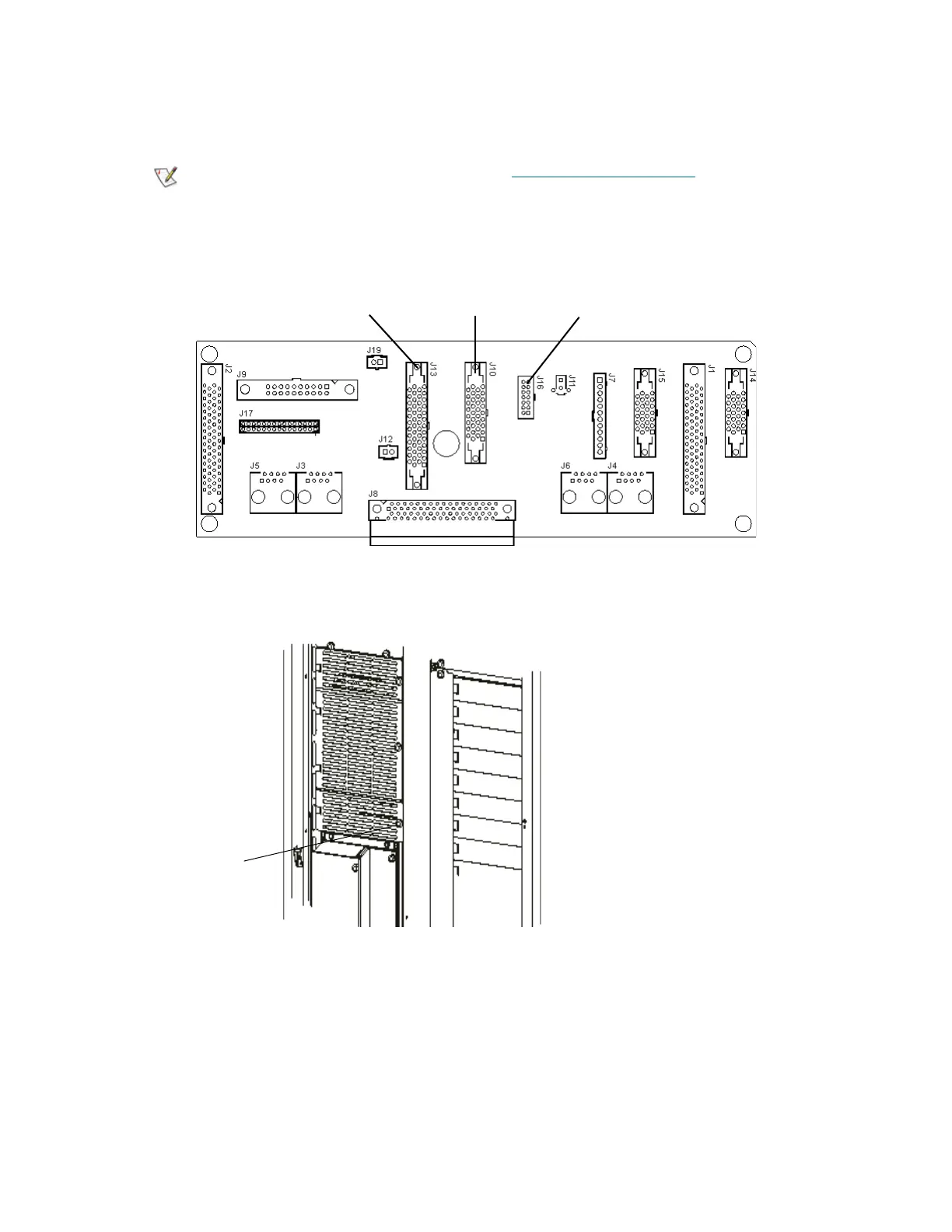
12 Connect the I/O management cables to the LBX board. This includes connecting the CAN cable (W7)
to J13, connecting the Ethernet cluster cable (W11) to J10, and connecting power supply status cable
(W16) to J16.
13 Insert and tighten the LBX/IEX cover plate using the thumbscrew.
Note
For more LBX version information, see LBX Board and Terminator on page
345.
connector: J13
plug: W7 to I/O
management unit
and CAN interface
connector: J10
plug W11 to I/O
management unit
and Ethernet
connector: J16
plug: W16 to power
supply status cable
from LBX board
LBX/IEX cover
plate thumbscrew

Table of Contents

Other manuals for Quantum Scalar i6000

Questions and Answers:

Question and Answer IconNeed help?

Do you have a question about the Quantum Scalar i6000 and is the answer not in the manual?

Quantum Scalar i6000 Specifications

General IconGeneral
Form FactorRack-mountable
InterfaceFibre Channel, SAS
Product TypeTape Library
CoolingRedundant cooling fans
DimensionsVaries by configuration
WeightVaries by configuration
Operating Humidity20% to 80% non-condensing
ScalabilityScalable
Drive TypesLTO
RedundancyRedundant power supplies
ManagementWeb-based management
Tape TechnologyLTO
Supported MediaLTO Ultrium 9, LTO Ultrium 8, LTO Ultrium 7, LTO Ultrium 6
Power SupplyRedundant power supplies
Non-operating Humidity5% to 95% non-condensing

Related product manuals