RADWIN2000+SeriesUserManual Release4.2.40 19‐4
AbouttheFresnelZone
19.4AbouttheFresnelZone
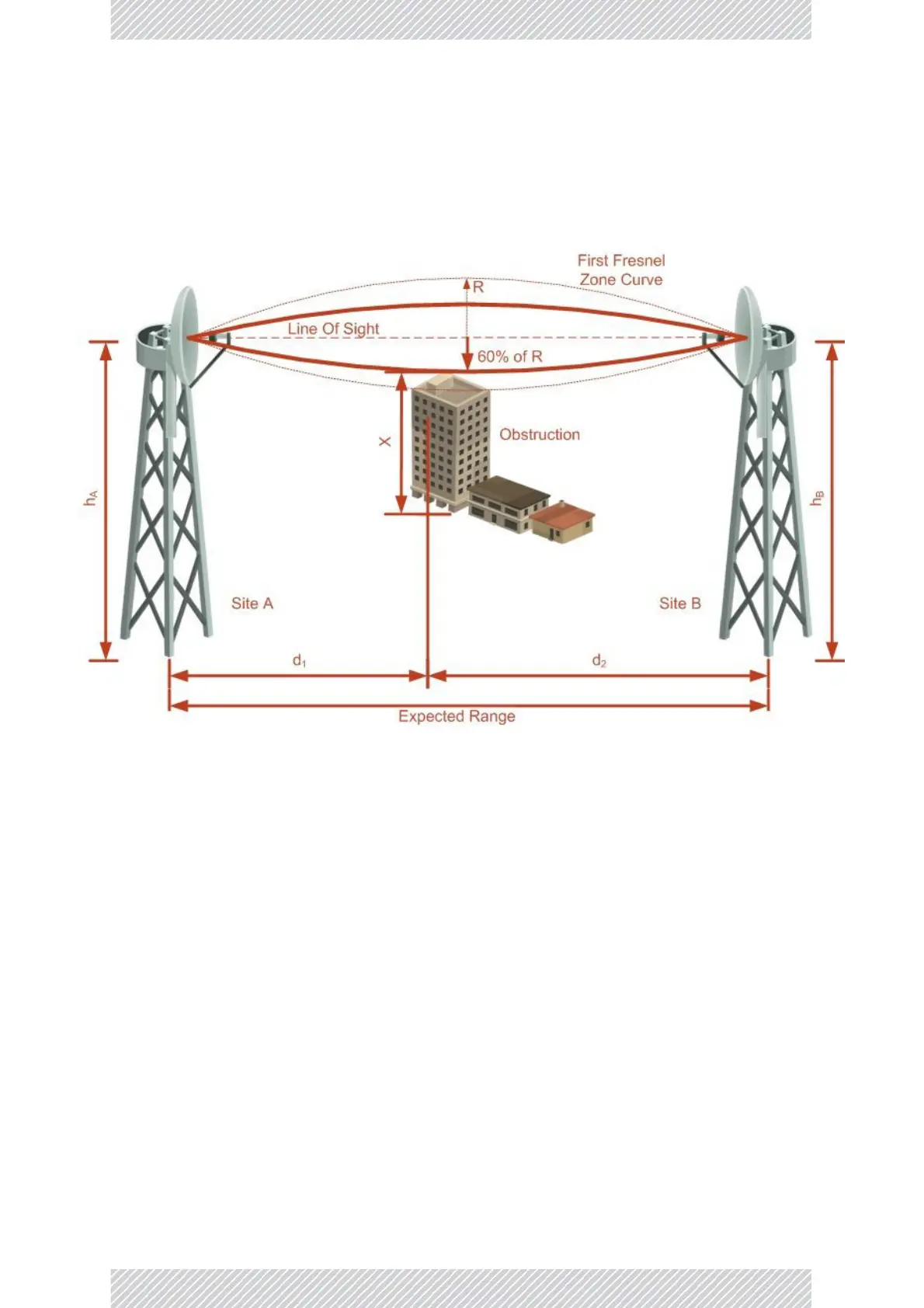
TheFresnelzoneisanellipticallyshapedconicalzoneofelectromagneticenergythat
propagatesfromthetransmittingantennatothereceivingantenna.Itisalwayswidestinthe
middleofthe pathbetweenthetwoantennas.
Figure19‐1:Fresnelzone
Fresnellossisthepathlossoccurringfrommulti‐pathreflectionsfromreflectivesurfaces
suchaswater,andinterveningobstaclessuchasbuildingsormountainpeakswithinthe
Fresnelzone.
Radiolinksshouldbedesignedtoaccommodateobstructionsandatmosphericconditions,
weatherconditions,largebodiesofwater,andotherre
flectorsandabsorbersof
electromagneticenergy.
TheFresnelzoneprovidesuswithawa ytocalculatetheamountofclearancethatawireless
waveneedsfromanobstacletoensurethattheobstacledoesnotattenuatethesignal.
ThereareinfinitelymanyFresnelzoneslocatedcoaxiallyaroundthecenterofthedir
ect
wave.TheouterboundaryofthefirstFresnelzoneisdefinedasthecombinedpathlengthof
allpaths,whicharehalfwa velength(1/2)ofthefrequencytransmittedlongerthanthe
directpath.Ifthetotalpathdistanceisonewavelength(1)longerthanthedirectpath,then
theouterboundaryissaidtobetwoFresnelzones.OddnumberFresnelzonesreinforcethe
directwavepathsignal;evennumberFresnelzonescancelthedirectwavepathsignal.
TheamountoftheFresnelzoneclearanceisdeterminedbythewavelengthofthesignal,the
pathlength,andthedistancetotheobstacle.Forreliability,point‐to‐pointlinksar edesigned
tohaveatleast60%ofthefirstFresnelzonecleartoavoidsignificantattenuation.