RADWIN2000+SeriesUserManual Release4.2.40 4‐22
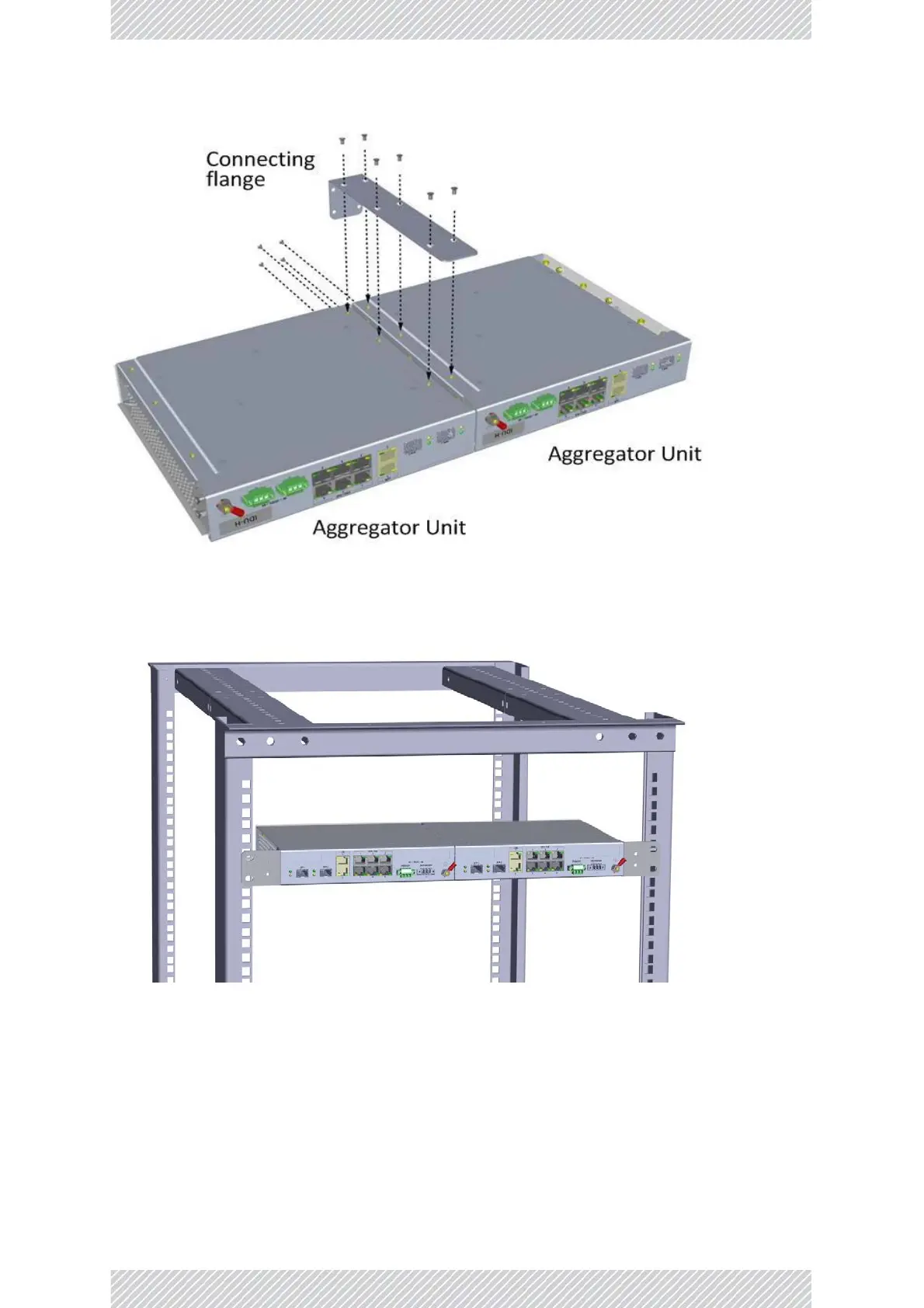
MountingtheIDU‐H/HPandRADWIN2000i
Figure4‐32:ConnectingtwoIDU‐H/HPunits
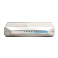
Figure4‐33:TwoIDU‐H/HPunitsmountedina19in.rack
MountingtheRADWIN2000i
TheRADWIN2000icanbemountedina19in.rack.Ittakesupthewholerackwidth.