MASTER FEED SECTION
C262/C265 3-52 SM
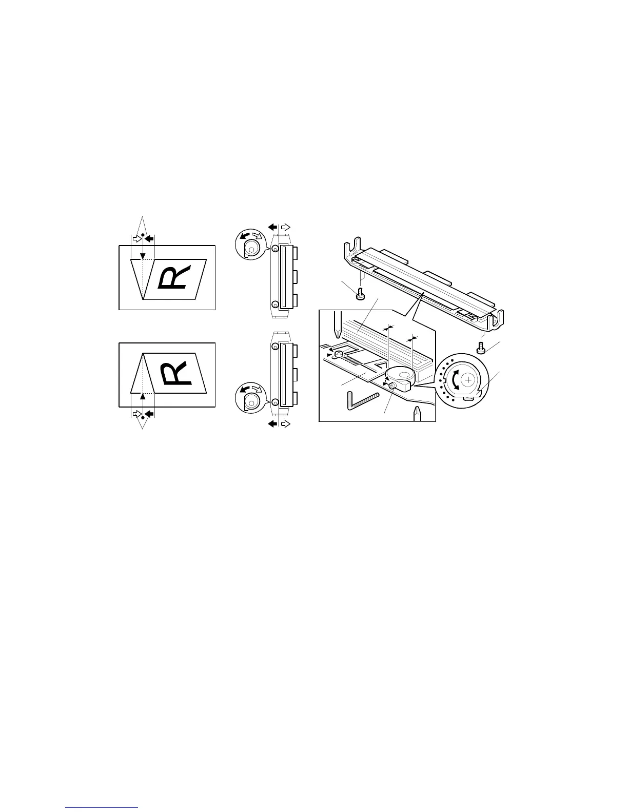
3.7.19 THERMAL HEAD ALIGNMENT ADJUSTMENT
Purpose: To make sure that the original image is correctly reproduced without
skew.
• Master making unit ( 3.7.1)
• Master making unit right cover ( 3.7.3)
• Thermal head cover ( 3.7.3)
• Thermal head base ( 3.7.3)
1. Remove the thermal head guide plate [A].
2. Loosen the four screws [B] that secure the thermal head base.
3. Loosen the Allen screws [C].
4. Turn the eccentric bushing [D] at the operation side or the non-operation side. If
the eccentric bushings [D] are turned one graduation, the image skew amount
[E] is corrected by 0.2 mm.
5. Tighten the Allen screws [C].
6. Tighten the four screws [B] that secure the thermal head base.
7. Install the thermal head guide plate [A].
NOTE: When you install the thermal head base and the thermal head guide
plate, make sure that these are positioned correctly ( 3.7.3).
8. Install the thermal head base, thermal head cover, and master making unit right
cover. ( 3.7.3)
9. Install the master making unit. ( 3.7.1)
10. Make a new master and checked if the image skew is correct.
C262R196.WMF
C262R195.WMF
[A]
[C]
[D]
[E]
[E]
[E]
[B]
[B]