MAIN DRIVE AND IMAGE UP/DOWN SHIFTING DRIVE SECTION
C262/C265 3-144 SM
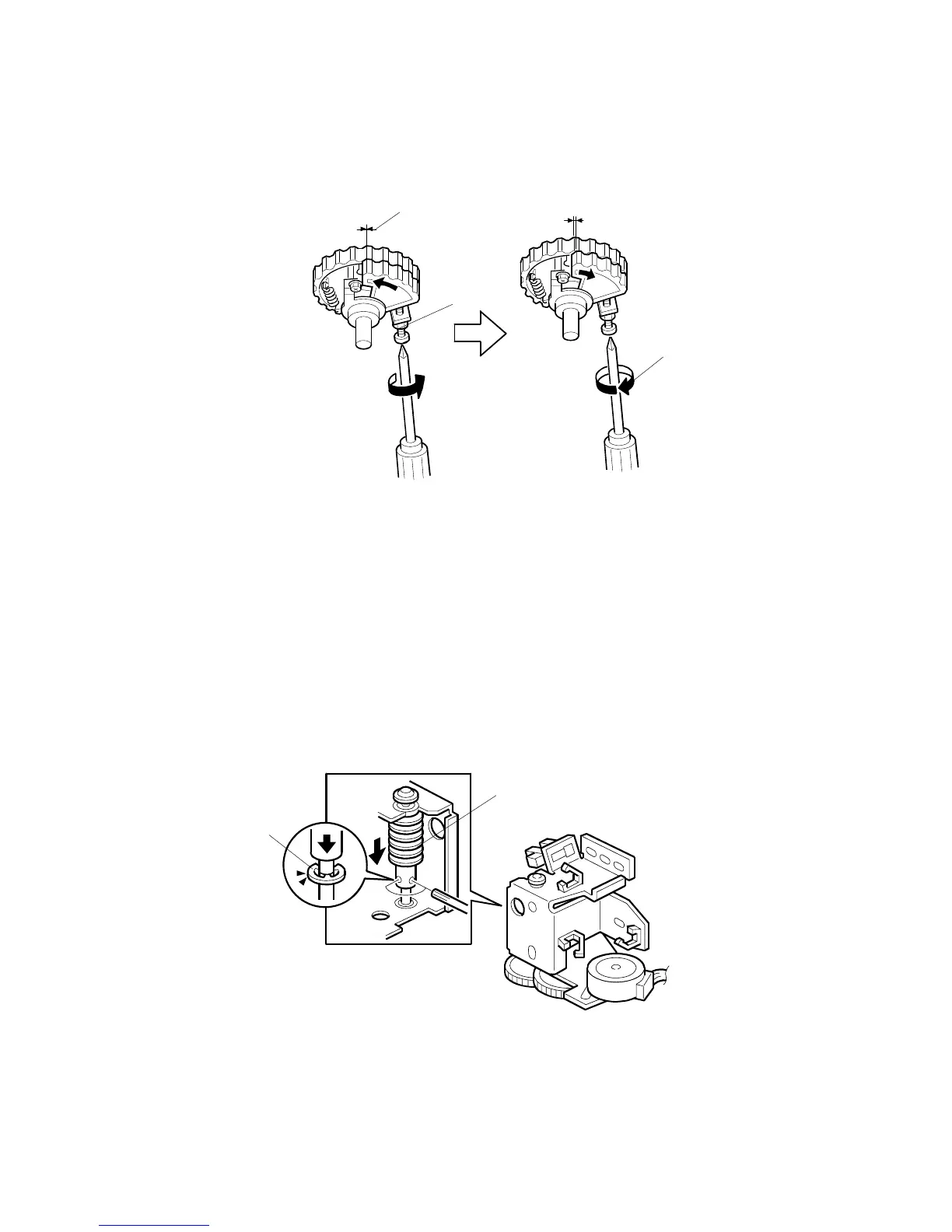
3.11.5 SCISSORS GEAR POSITION ADJUSTMENT
Purpose: If the position of the scissors gear is not correct, the paper feed
registration will vary.
1. Loosen the lock nut [A].
2. Tighten the screw, so that the gear meshes on both gears are aligned as
shown [B].
3. Turn the screw fully counterclockwise circle to loosen it, as shown [C].
4. Holding the screw, tighten the lock nut [A].
3.11.6 IMAGE UP/DOWN SHIFT WORM-GEAR POSITION
ADJUSTMENT
Fully push down the worm gear [A], and push down E-ring [B] of the worm gear
shaft. While holding them together, secure with the 2 hexagon screws.
C262R121.WMF
C262R120.WMF
[A]
[B]
[A]
[B]
[C]