Digital Modules
3-24
Programmable Logic Controllers S7-300 Module Data
A5E00105505-03
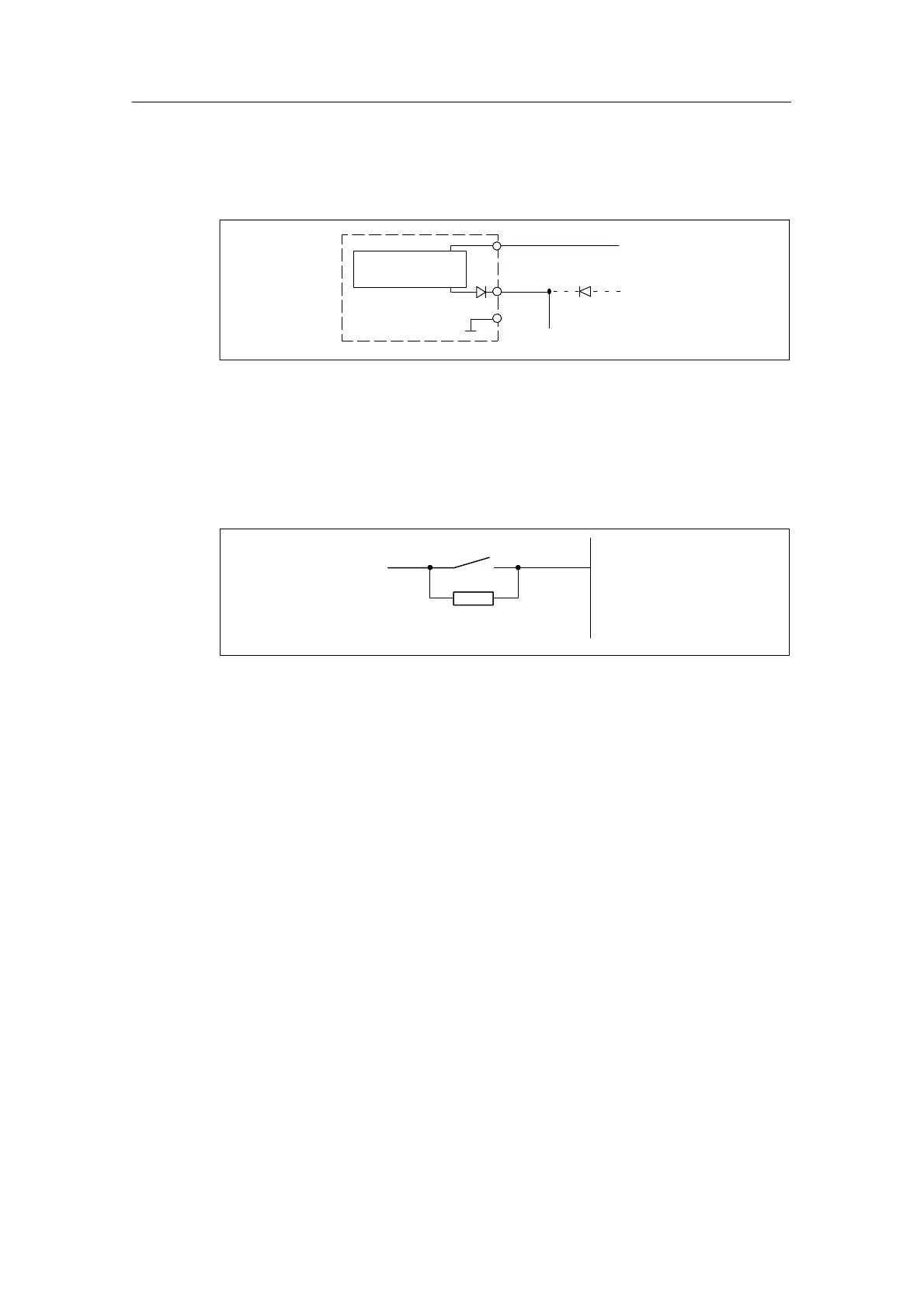
Terminal assignment for redundant supply of encoders
The figure below shows how encoder can additionally be supplied by means of Vs
with a redundant voltage source – for example, via another module).
Vs
M
L+
1 L+
2 L+
to the sensors
±
Digital input
module
Short-circuit-
proof driver
Figure 3-7 Terminal assignment for redundant supply of encoders of SM 321;
DI 16 x VDC 24
Terminal assignment for resistive circuit of the encoder
In order to detect a broken wire, it is necessary to wire the encoder contact with a
resistor.
L +/ V
s E
x.x
15
k
...
18
k
Figure 3-8 Terminal assignment for resistive circuit of the encoder of the SM 321;
DI 16 x 24 VDC

 Loading...


