Diagnostics Data of Signal Modules
B-5
Programmable Logic Controllers S7-300 Module Data
A5E00105505-03
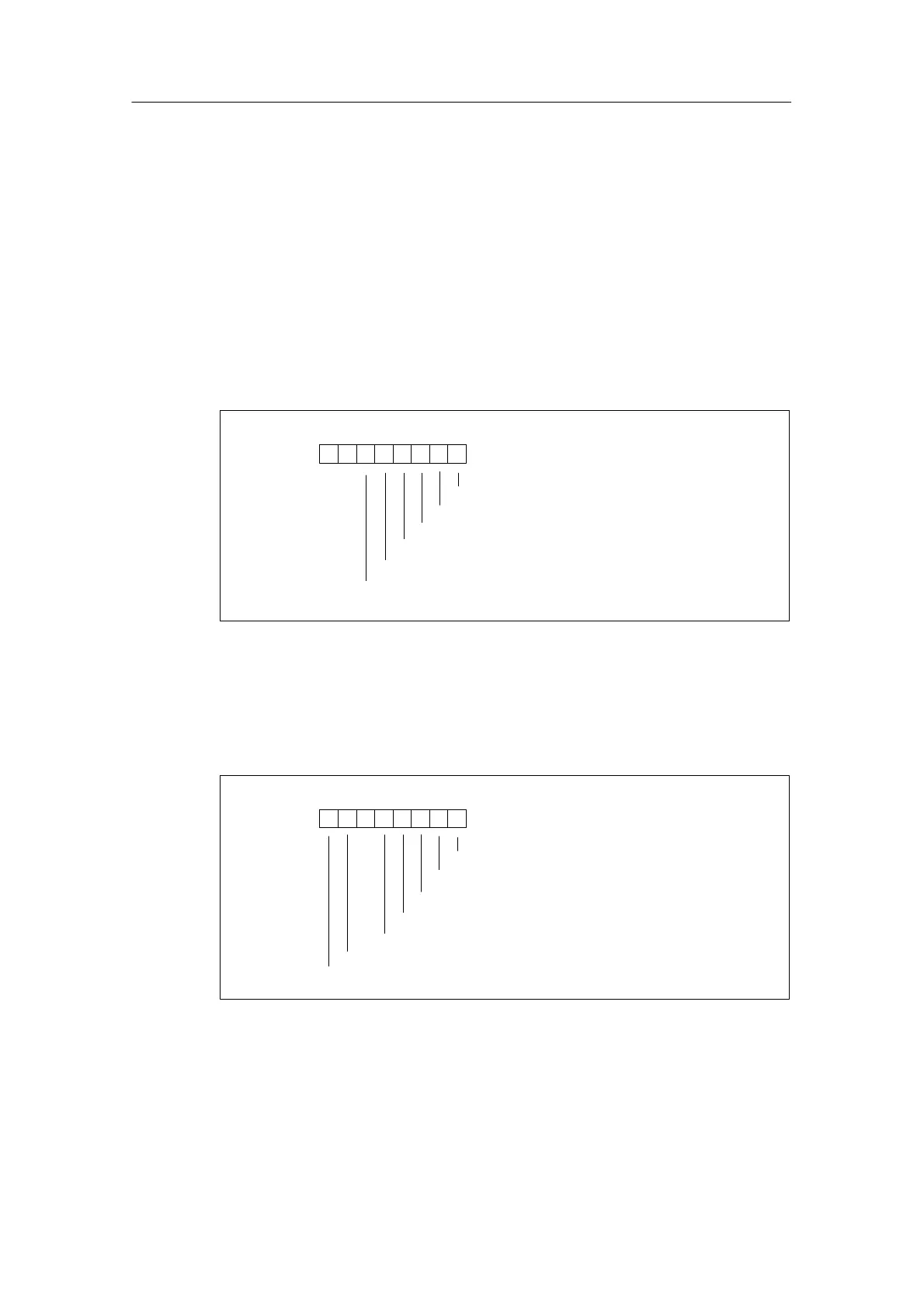
B.3 Channel-Specific Diagnostic Data from Byte 8
From byte 8 up to byte 15, data record 1 contains the channel-specific diagnostic
data. The figures below show the assignment of the diagnostic byte for a channel
or a channel group of the specific module. The following general rule applies:
When an error occurs, the bit concerned is set to “1”.
You will find a description of possible error causes and appropriate remedies in the
section called “Diagnostics of the Modules”.
Digital input channel of the SM 321; DI 16 24 VDC; with hardware and
diagnostic interrupts
76 0
Sensor supply missing
54321
00
Configuring/parameter assignment error
Ground fault
Wire-break
Short-circuit to L+
Short-circuit to M
Figure B-4 Diagnostic Byte for a Digital Input Channel of the SM 321; DI 16 x 24 VDC
Digital output channel of the SM 322; DO 8 x 24 VDC/0.5 A; with diagnostic
interrupt
76 0
Short-circuit to L+
Short-circuit to M
Wire-break
External auxiliary supply missing
54321
0
Configuring/parameter assignment error
Ground fault
Overtemperature
Figure B-5 Diagnostic Byte for a Digital Output Channel of the SM 322;
DO 8 x 24 VDC/0.5 A

 Loading...


