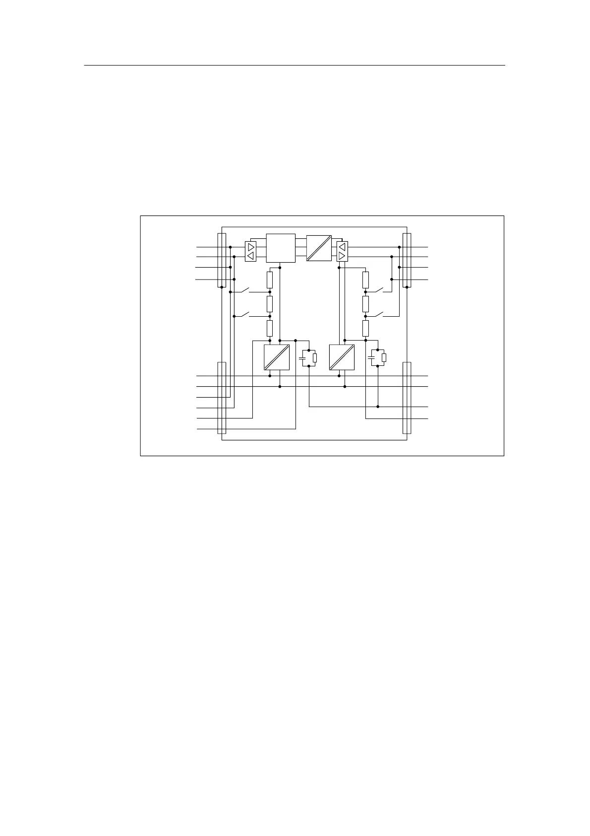
EasyManuals Logo

Siemens SIMATIC S7-300 Module data Reference Manual

Siemens SIMATIC S7-300 Module data
574 pages
To Next Page IconTo Next Page
To Previous Page IconTo Previous Page
Page #443 background imageLoading...
Page #443 background image
RS 485 Repeater
7-7
Programmable Logic Controllers S7-300 Module Data
A5E00105505-03
Block diagram of the RS 485 repeater
Bus segment 1 and bus segment 2 are galvanically isolated from each other.
Bus segment 2 and the PG/OP socket are galvanically isolated from each
other.
Signals are amplified
between bus segment 1 and bus segment 2
between PG/OP socket and bus segment 2
5V
24V
Segment 2
A2
B2
A2
B2
Segment 1
A1
B1
A1
B1
PG/OP-
socket
L+ (24 V)
M
A1
B1
5 V
M5 V
L+ (24 V)
M
PE
M 5.2
Logic
5V
24V
1M1M
Figure 7-3 Block diagram of the RS 485 repeater

Table of Contents

Other manuals for Siemens SIMATIC S7-300 Module data

Questions and Answers:

Question and Answer IconNeed help?

Do you have a question about the Siemens SIMATIC S7-300 Module data and is the answer not in the manual?

Siemens SIMATIC S7-300 Module data Specifications

General IconGeneral
SeriesS7-300
ManufacturerSiemens
Protection ClassIP20
SystemSIMATIC S7-300
Digital InputsVaries by module
Digital OutputsVaries by module
Analog InputsVaries by module
Analog OutputsVaries by module
Central Processing UnitVaries by CPU model
Supply Voltage24V DC or 120/230V AC
CPU TypeVaries (e.g., CPU 312, CPU 315, etc.)
MemoryVaries by CPU model
Communication InterfacesMPI, PROFIBUS
Programming LanguagesLAD, FBD, STL, SCL, GRAPH
Operating Temperature0°C to 60°C
Storage Temperature-40°C to 70°C
Relative Humidity10% to 95% (non-condensing)

Related product manuals