Analog Modules
4-58
Programmable Logic Controllers S7-300 Module Data
A5E00105505-03
4.12 Connecting Thermocouples
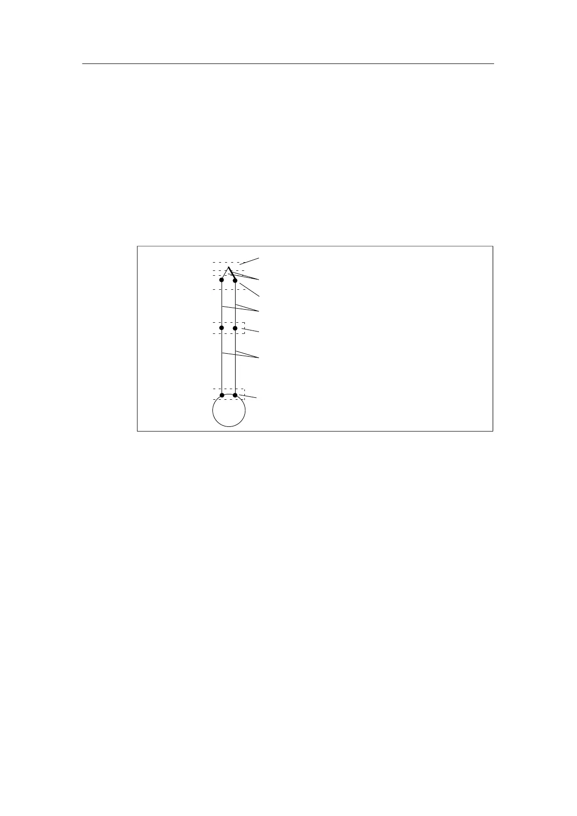
Design of thermocouples
A thermocouple consists of a pair of sensors and the necessary installation and
connecting parts. The thermocouple consists of two wires of dissimilar metals or
metal alloys soldered or welded together at the ends.
There are different types of thermocouple, depending on the composition of the
material used – for example, K, J, N thermocouples. The measuring principle of all
thermocouples is the same, irrespective of their type.
° C
Leads
Compensating leads
Reference junction
Connecting point
Thermocouple with positive or negative limbs
Measuring junction
Point at which thermo-e. m. f. is measured
Figure 4-22 Design of Thermocouples
Principle of Operation of Thermocouples
If the measuring point is subjected to a temperature different from that of the free
ends of the thermocouple (point of connection), a voltage, the thermo emf, occurs
at the free ends. The magnitude of the thermo-e.m.f. generated depends on the
difference between the temperature at the measuring junction and the temperature
at the free ends, as well as on the material combination used for the thermocouple.
Since a thermocouple always measures a temperature difference, the free ends
must be kept at a known temperature at a reference junction in order to determine
the temperature of the measuring junction.
The thermocouples can be extended from their point of connection to the reference
junction by means of compensating wires. These compensating wires consist of
the same material as the thermocouple wires. The supply leads are copper wire.
Note: Make sure these wires are connected with the correct polarity, otherwise
there will be considerable measuring errors.