EasyManua.ls Logo

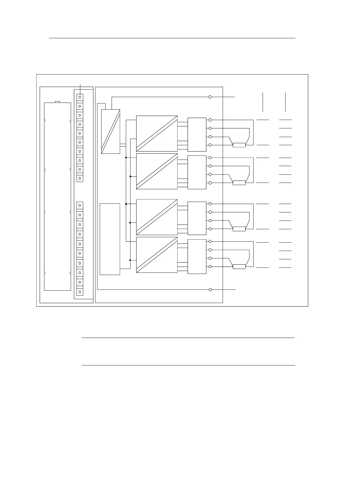
Siemens SIMATIC S7-300 Module data - Module View and Block Diagram of the SM 332; AO 4 X 16 Bits

Siemens SIMATIC S7-300 Module data
574 pages
To Next Page IconTo Next Page
To Previous Page IconTo Previous Page
Loading...
Analog Modules
4-170
Programmable Logic Controllers S7-300 Module Data
A5E00105505-03
Terminal connection and block diagram of analog output module SM 332;
AO 4 x 16 bit
SF
QI
0
Isolation
CH0
CH0
Current
Outputs
Voltage
Outputs
M
ANA 0
QV
0
S
0
+
S
0
M
ANA 0
Fault indicator – red
QI
1
CH1
CH1
M
ANA 1
QV
1
S
1
+
S
1
M
ANA 1
QI
2
CH2
CH2
M
ANA 2
QV
2
S
2
+
S
2
M
ANA 2
QI
3
CH3
CH3
M
ANA 3
QV
3
S
3
+
S
3
M
ANA 3
L+
24 V
M
1
3
4
5
6
7
8
9
10
11
12
13
14
15
16
17
18
20
Back-
plane
bus
inter-
face
Figure 4-51 Module View and Block Diagram of the SM 332; AO 4 x 16 bits
Note
Switching the rated load voltage (L+) off and on for approx. 10 ms can lead to
incorrect intermediate values at the output.

Table of Contents

Other manuals for Siemens SIMATIC S7-300 Module data

Related product manuals