Analog Modules
4-70
Programmable Logic Controllers S7-300 Module Data
A5E00105505-03
4.15 Connecting Loads/Actuators to Current Outputs
Note
The necessary connecting cables, which result from the potential connection of the
analog output module, are not drawn in the figures shown below.
In other words, you must continue to take note of and implement Section 4.13 with
its generally valid information for connecting loads and actuators.
Abbreviations and mnemonics used in the figures below
The abbreviations and mnemonics used in the figures below have the following
meanings:
Q
I
: Analog output current
M
ANA
: Reference potential of analog circuit
R
L
: Load impedance
L +: Terminal for 24 VDC supply voltage
M : Ground terminal
U
ISO
: Potential difference between M
ANA
and M terminal of CPU.
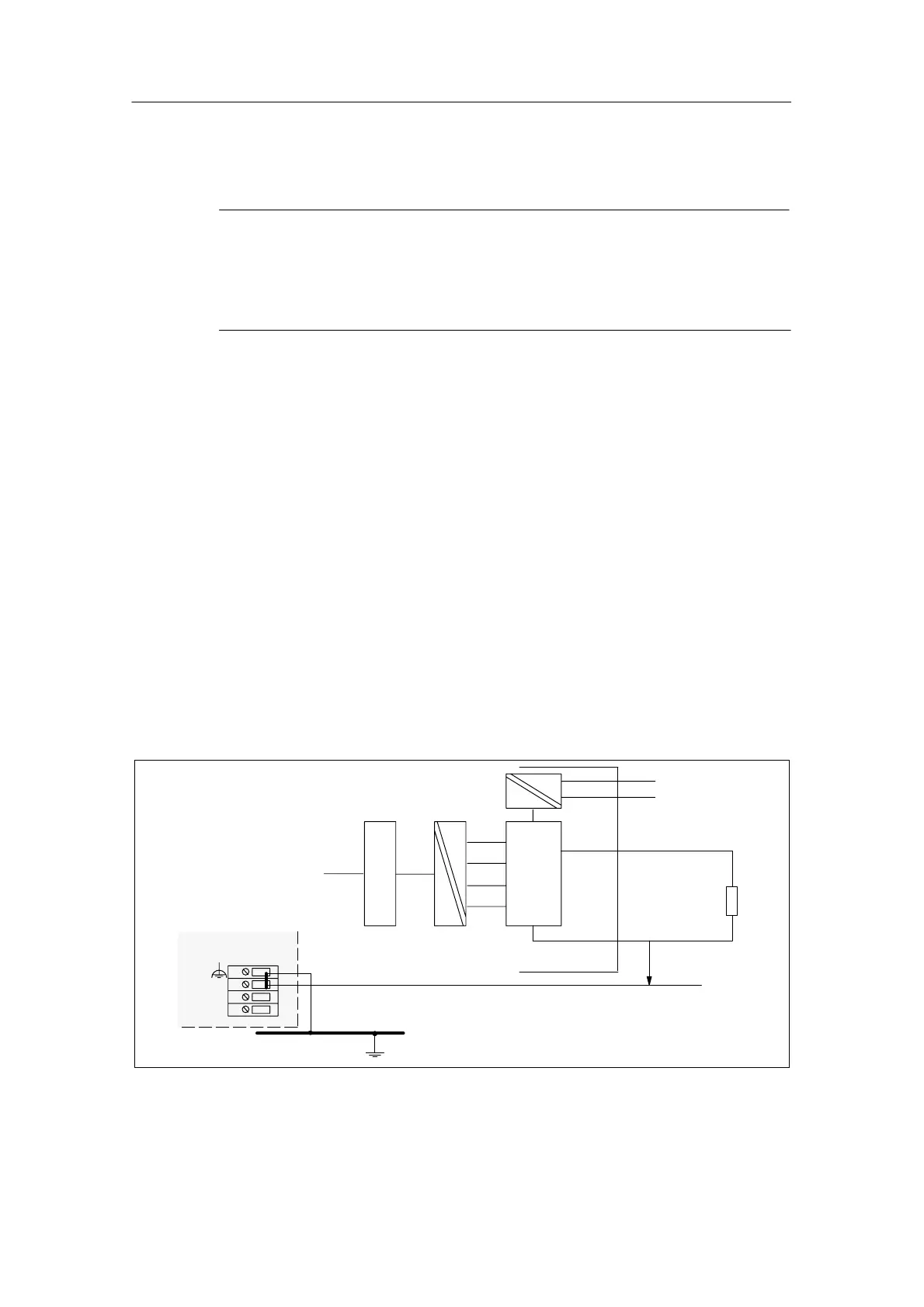
Connecting Loads to a Current Output
You must connect loads to Q
I
and the reference point of the analog circuit M
ANA
of
a current output.
M
L+
Backplane
bus
DAC
R
L
Q
I
M
ANA
M
internal
L+
M
Ground bus
CPU
U
ISO
Logic
Figure 4-30 Connecting Loads to a Current Output of an Isolated AO