Analog Modules
4-95
Programmable Logic Controllers S7-300 Module Data
A5E00105505-03
Wire–break check
The wire-break check is a module software function that is available for all the
voltage ranges and the current range of 4 to 20 mA.
• With the ± 5 V, 1 to 5 V or ± 10 V measuring ranges and an enabled wire-break
check, the isolated analog input module enters a wire-break in the diagnosis
when the process value achieves a positive full-scale deflection (32768). If you
enabled the diagnostic interrupt during configuration, the analog input module
also triggers a diagnostic interrupt.
If the diagnostic interrupt has not been enabled, the illuminated SF display is
the only indication that there is a wire-break. You must then analyze the
diagnosis bytes in the user program.
• With a measuring range of 4 to 20 mA and an enabled wire-break check, the
isolated analog input module enters wire-break in the diagnosis when the
process value falls below 3.6 mA. If you enabled the diagnostic interrupt during
configuration, the analog input module also triggers a diagnostic interrupt.
If the diagnostic interrupt has not been enabled, the illuminated SF display is
the only indication that there is a wire-break. You must then assess the
diagnosis bytes in the user program.
• If the wire-break check is not enabled, the isolated analog input module triggers
a diagnostic interrupt if the limit value for underflow is not reached.
Measuring ranges
You perform setting of the measuring ranges with the “measuring range” parameter
in STEP 7.
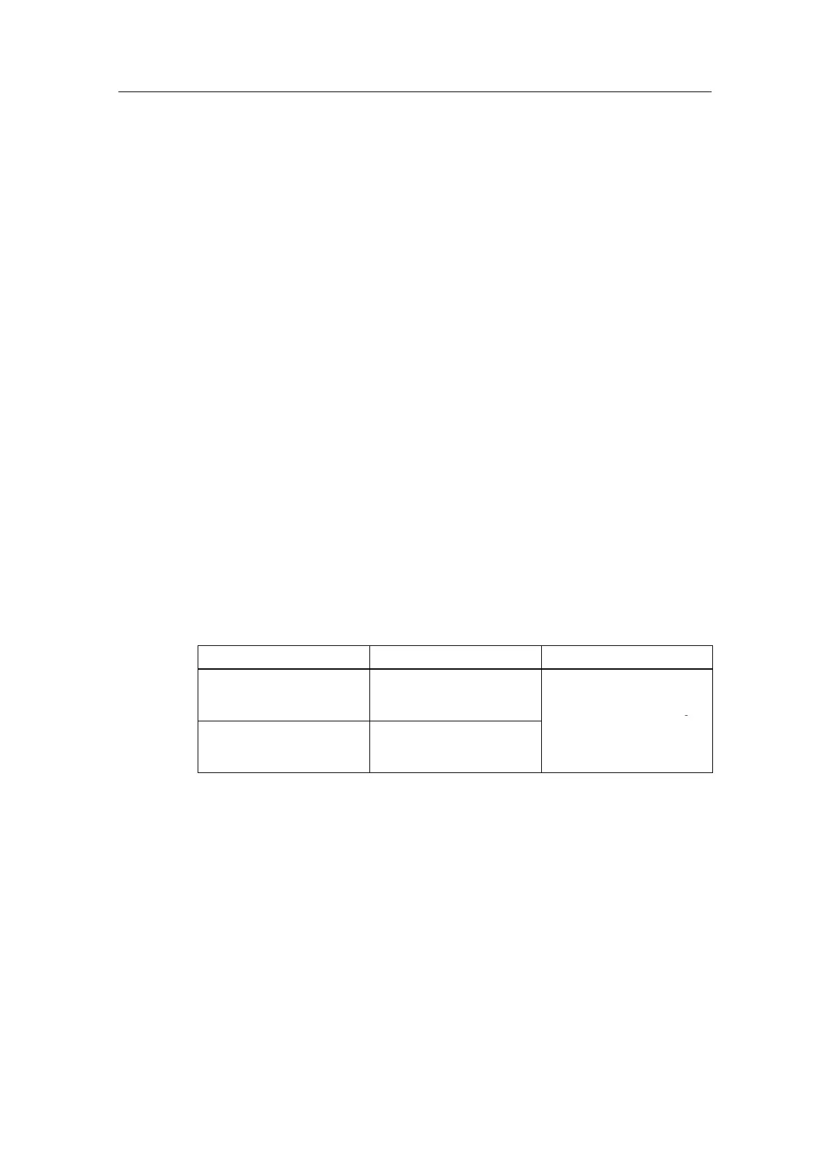
Table 4-57 Measuring ranges of the SM 331; AI 8 x 16 bits
Method Selected
Output Range Description
Voltage " 5 V
From 1 to 5 V
" 10 V
You will find the digital
analog values from
Section 4.3.1 in the voltage
and current output ranges
Current (4-wire transmitter) From 0 to 20 mA
From 4 to 20 mA
" 20 mA
Section 4.3.1 in the voltage
and current output ranges