Digital Modules
3-27
Programmable Logic Controllers S7-300 Module Data
A5E00105505-03
3.9.2 Assigning Parameters to SM 321; DI 16 x VDC 24
Parameter assignment
You will find a description of the general procedure for assigning parameters to
digital modules in the reference manual, section 3.3.
Parameters of the SM 321; DI 16 x 24 VDC
You will find an overview of the parameters that you can set and their default
settings for the SM 321; DI 16 x 24 VDC in the table below.
The default settings apply if you have not performed parameter assignment in
STEP 7.
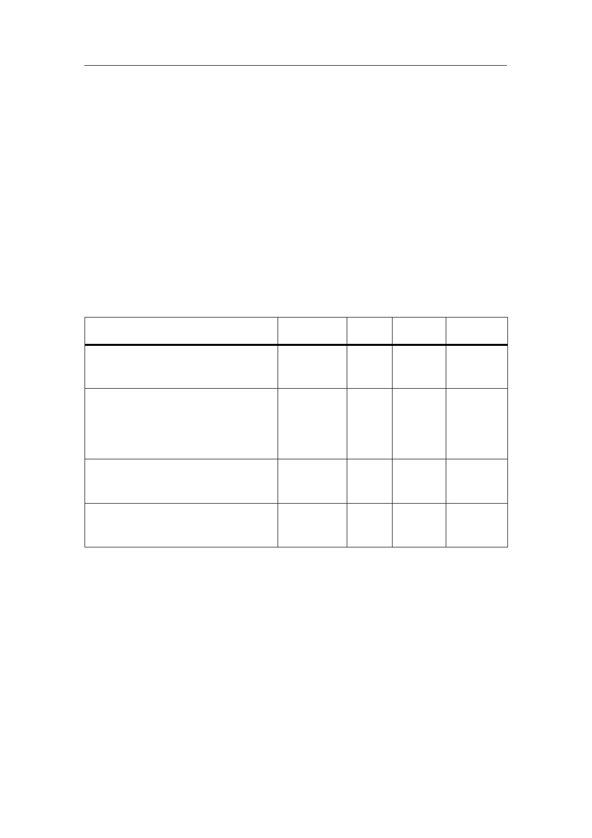
Table 3-8 Parameters of the SM 321; DI 16 x VDC 24
Parameter
Value Range Default
Settings
Parameter
Type
Scope
Enable
• Diagnostic interrupt
• Hardware interrupt
Yes/no
Yes/no
No
No
Dynamic Module
Input delay/voltage type 0.1 ms (DC)
0.5 ms (DC)
3 ms (DC)
15 ms (DC)
20 ms (DC/AC)
(DC) Static Module
Diagnostics
• Sensor supply missing
• Wire-break
Yes/no
Yes/no
No
No
Static Channel
group
Trigger for hardware interrupt
• Rising edge
• Falling edge
Yes/no
Yes/no
No
No
Dynamic Channel
group
Assignment of the encoder supplies to channel groups
The two encoder supplies of the module are used to supply two channel groups:
inputs 0 to 7 and inputs 8 to 15. In these two channel groups, you parameterize the
diagnostics for the encoder supply, too.
Assigning interrupt parameters to channel groups
The table below shows the channels that can be combined to form a channel
group if you would like to parameterize interrupt processing.
You will need the channel group number to set the parameters in the user program
with an SFC.