SIMATIC TOP Connect and SIMATIC TOP Connect TPA
8-5
Programmable Logic Controllers S7-300 Module Data
A5E00105505-03
Cable sheath to
be removed
external
ribbon
cable
internal
ribbon
cable
external
ribbon
cable
internal
ribbon
cable
Cable end to ...
20-pin
front
connec-
tor
40-pin
front
connec-
tor
20-pin
front connector
40-pin
front connector
... top connector of front
connector module
1 x 16 core
110 mm 115 mm
... bottom connector of
front connector module
shielded/uns
hielded
70 mm 75 mm
... top connector of front
connector module
95 mm 115 mm
... bottom connector of
front connector module
2 x 16 core
unshielded
95 mm 115 mm
40 mm 75 mm
... socket of terminal
block
40 mm 100 mm
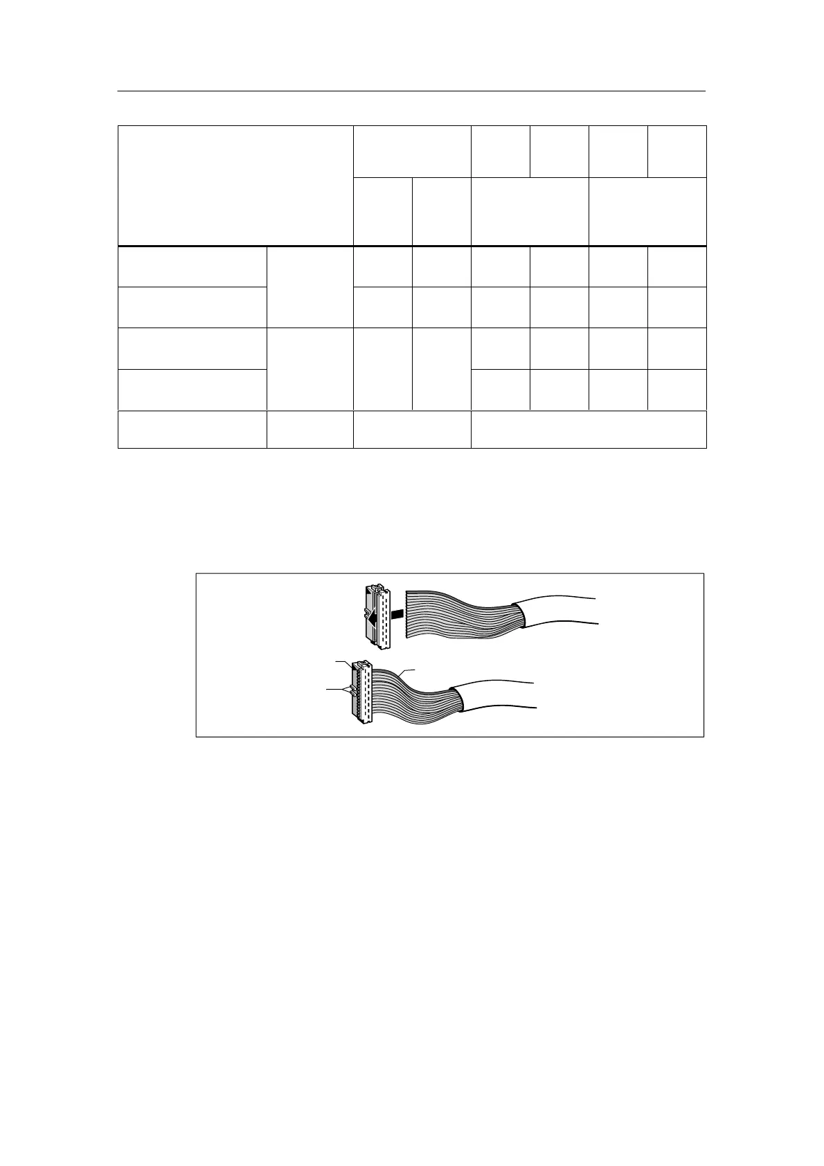
2. Thread the cable into the 16-pin connector.
It is important that you note the position of the details marked in the following
figure.
Triangle
Nose
Marked Core
Figure 8-2 Threading the Round-Sheath Ribbon Cable into the Connector
3. Clamp the end of the cable into the connector with the crimping tool.
4. Attach the strain relief device to the connector of the terminal block as follows:
– Fold back the cable over the connector
– Push the enclosed strain relief device over the cable
– Snap the strain relief device into place on the connector