EasyManuals Logo

Siemens SIMATIC S7-300 Module data Reference Manual

Siemens SIMATIC S7-300 Module data
574 pages
To Next Page IconTo Next Page
To Previous Page IconTo Previous Page
Page #98 background imageLoading...
Page #98 background image
Digital Modules
3-14
Programmable Logic Controllers S7-300 Module Data
A5E00105505-03
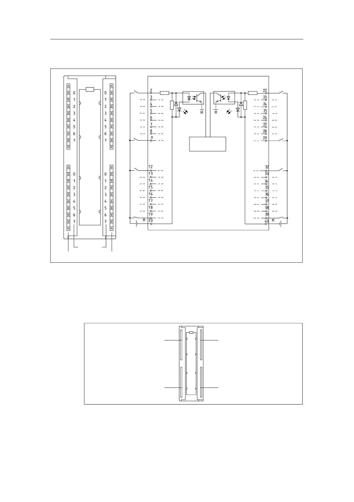
Terminal assignment and block diagram of the SM 321; DI 32 x 24 VDC
Channel
number
Status display – green
Backplane bus
interface
24V
24V
Figure 3-1 Module View and Block Diagram of the Digital Input Module SM 321; DI 32 x 24 VDC
Terminal assignment of the SM 321; DI 32 x 24 VDC
The following figure shows the assignment of the channels to the addresses.
Input byte x
Input byte (x+1)
Input byte (x+2)
Input byte (x+3)
Figure 3-2 Terminal assignment of the SM 321; DI 32 x 24 VDC

Table of Contents

Other manuals for Siemens SIMATIC S7-300 Module data

Questions and Answers:

Question and Answer IconNeed help?

Do you have a question about the Siemens SIMATIC S7-300 Module data and is the answer not in the manual?

Siemens SIMATIC S7-300 Module data Specifications

General IconGeneral
SeriesS7-300
ManufacturerSiemens
Protection ClassIP20
SystemSIMATIC S7-300
Digital InputsVaries by module
Digital OutputsVaries by module
Analog InputsVaries by module
Analog OutputsVaries by module
Central Processing UnitVaries by CPU model
Supply Voltage24V DC or 120/230V AC
CPU TypeVaries (e.g., CPU 312, CPU 315, etc.)
MemoryVaries by CPU model
Communication InterfacesMPI, PROFIBUS
Programming LanguagesLAD, FBD, STL, SCL, GRAPH
Operating Temperature0°C to 60°C
Storage Temperature-40°C to 70°C
Relative Humidity10% to 95% (non-condensing)

Related product manuals