Parameter Sets for Signal Modules
A-35
Programmable Logic Controllers S7-300 Module Data
A5E00105505-03
Module modes
Table A-24 contains the codes for the module modes, which you enter in byte 0 of
data record 128 (see Figure A-14).
Table A-24 Codes for the modes of SM 331; AI 8 x 16 bits
Module mode
Code
8 channels 2#00000000
4 channels 2#00000001
Interference suppression
Table A-25 contains the codes for the different frequencies, which you enter in byte
1 of data record 128 (see Figure A-14). Note that 4-channel mode only functions if
interference frequency suppression of 50, 60 and 400 Hz is set.
Table A-25 Codes for interference frequency suppression of the SM 331; AI 8 x 16 bits
Interference Suppression
Code
400 Hz 2#00
60 Hz 2#01
50 Hz 2#10
50, 60 and 400 Hz 2#11
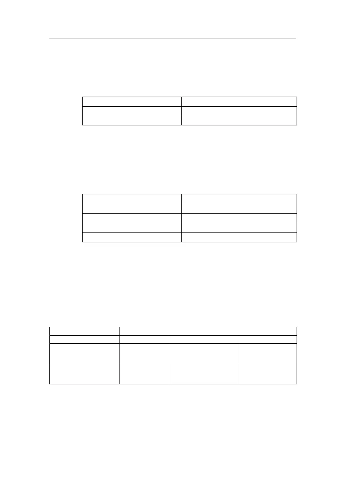
Measuring methods and measuring ranges
Table A-26 contains all the measuring ranges for the isolated analog input module
SM 331; AI 8 x 16 bits. Table A-26 also shows the codes for measuring methods
and measuring ranges. You must enter these codes in accordance with the
required measuring range in the relevant byte of data record 128
(see Figure A-14).
Table A-26 Codes for the measuring ranges of the SM 331; AI 8 x16 bits
Measuring Method
Code Measuring Range Code
Deactivated 2#0000 Deactivated 2#0000
Voltage 2#0001 ± 5 V
1 to 5 V
± 10 V
2#0110
2#0111
2#1001
Current (4-wire transmitter) 2#0002 0 to 20 mA
4 to 20 mA
± 20 mA
2#0010
2#0011
2#0100
Settings for input smoothing
Table A-27 contains all the smoothing settings for the isolated analog input module
SM 331; AI 8 x 16 bits. According to the smoothing required, you must enter these
codes in the corresponding byte of data set 128 (see imag eA-14.